Getting Started
Powering the Pilot Plug On
On the front side, there is a small switch next to the USB Type C ports (Figure 1.1). By default, it is in the “off”
position (left).
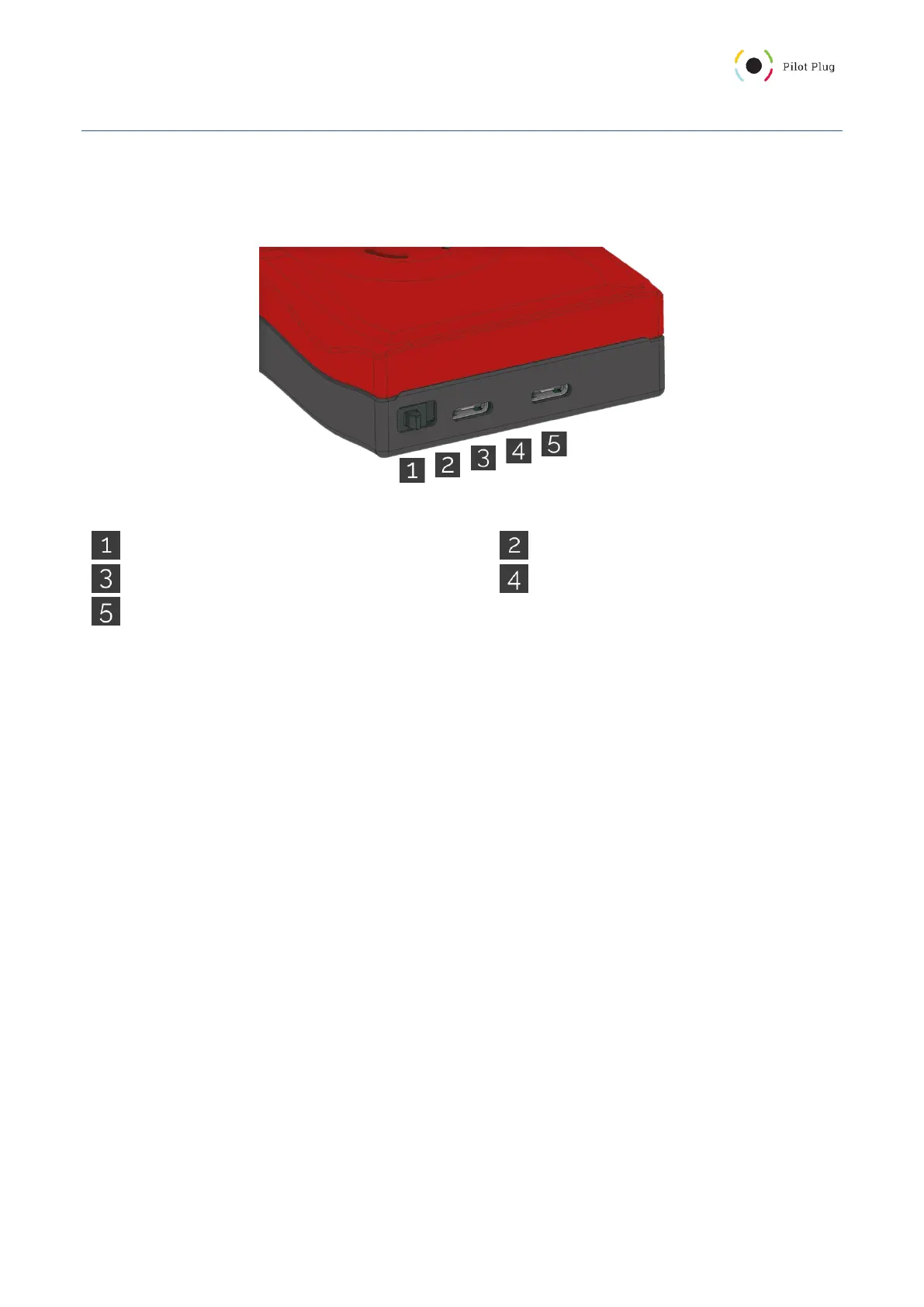
Figure 1: Pilot Plug Connection interface
Power Switch (left is off, right is on)
USB Type C (AIS or power input)
Charging LED (red = charging, green = full)
USB Type C (AIS or power input, USB communication)
Once you switch it to the right side, your Pilot Plug will begin its startup sequence. The startup sequence consists
of the following steps:
1. Software check (followed by a circle animation)
2. Configuration check (followed by a circle animation)
3. Hardware (sensor) check (followed by a circle animation)
4. local Rate of Turn calibration (all LEDs turned on)
5. startup melody
The circle animation turns all the LEDs on and then back off again. After you hear the startup sound (or melody),
the Pilot Plug is ready for incoming connections and transmits data.