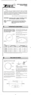
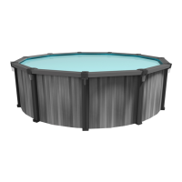
Insert the wall tracks on the circular stem of the joiner
plates. Make sure to completely snap the tracks on the
plates to securise installation (See Illustration 4.1).
Make a complete circle, using half of the wall tracks and
joiner plates found in the pool kit (See Chart and
Illustration 4.2).
4
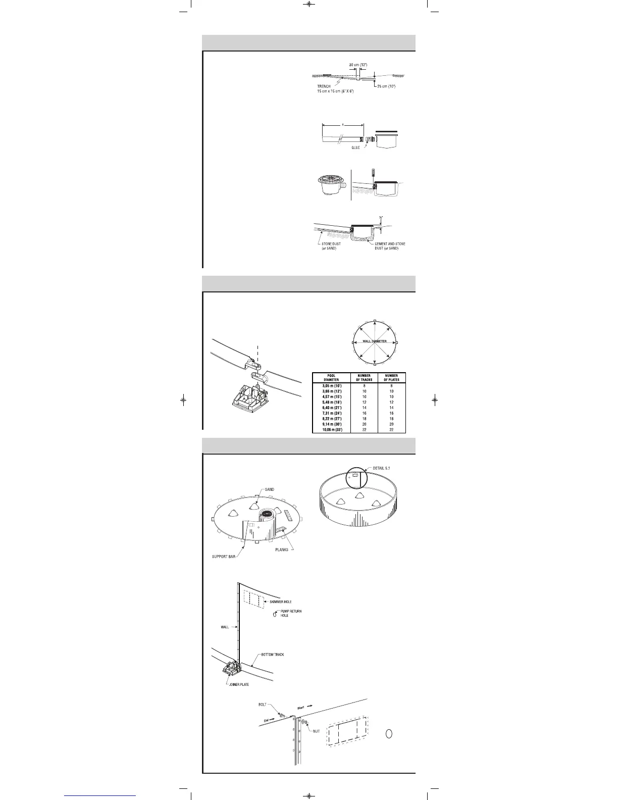
Before uncoiling the wall, make sure the pre-punched
holes for the skimmer and pump return are at the top and
facing the planned location of your filter.
Begin inserting the wall into the bottom wall tracks in the
middle of a joiner plate. At first, the wall should be kept in
place with one or two support bars (or extra persons).
One person should uncoil the wall on a beam or a plank
while a second person inserts it in the bottom wall tracks.
Do not uncoil more than 3 m (10') of wall before you
install a support bar to reinforce the structure.
Once the wall is completely uncoiled, you may find that it
is too long or that both ends do not meet by a few
centimetres. If such is the case, you must gently push the
wall in or out. If this does not work, roll up the wall again,
realign the grooves and uncoil the wall once more. If the
spread is too wide, measure the wall and check it against
the following chart.
When you prepare to join the ends of the wall, make sure
the end that is reinforced by the fold is inside the circle,
facing the liner and that the other end faces outward (See
Illustration 5.1). When the wall joint is screwed, install the
round stabiliser on top of it.
IMPORTANT: Due to the enormous pressure exerted by
the water on the steel wall, it is absolutely essential that all
bolts are screwed in tightly and that no hole is left open.
All bolt heads must be inside with washer and nut outside.
Cover all bolt heads with heavy fabric tape.
5
Illustration 4.1
Illustration 4.2
Inside
Outside
Chart
Illustration 5.1
Inside
Outside
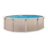
Dig a hole 30 cm (12") wide by approximately 25 cm
(10") deep in the center of the circumference.
From the center hole to the projected location of the pool
motor, dig a 15 cm (6") wide trench. Place the removed
s
oil aside to be used later to cover the hose.
B
ottom Drain Assembly
P
lace teflon around the threaded plug. Screw in drain
h
oles using large pliers. Glue the connector in the
appropriate opening.
T
ake one of the two rubber rings and adjust it to the top of
the drain, aligning the holes carefully. Secure with strips
of adhesive tape to prevent sand from penetrating inside
the holes once the drain has been installed.
Secure one end of the long black or white hose inside the
d
rain spout. First apply glue on the drain spout and inside
the drain end, then secure with one or two collars.
C
ut the hose so that it ends with the stone dust (or sand).
Measure the pool radius from the center of the drain, then
add 15 cm (6").
Place the assembled bottom drain in the hole so that it is
approximately 1.3cm (1/2") higher than the surface soil.
B
ury the hose, levelling the drain as much as possible.
Compact the soil, using your feet and a tampering tool as
well.
Mix three (3) shovels of stone or sand dust with one half
shovel of pure cement, adding a small quantity of water,
then pour the cement around the drain until it reaches 1.3
cm (1/2") from the top.
! %%"!"
3
 Loading...