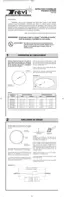
1) Dump the sand.
2) Choose the filter location beside a round section (never a straight
section). The starting point will be at that location so that the skim-
mer and return holes are as close as possible to the filtration sys-
tem.
3) Before uncoiling the wall, make sure the pre-punched holes for
the skimmer and pump return are at the top and facing the planned
location of your filter.
$
4
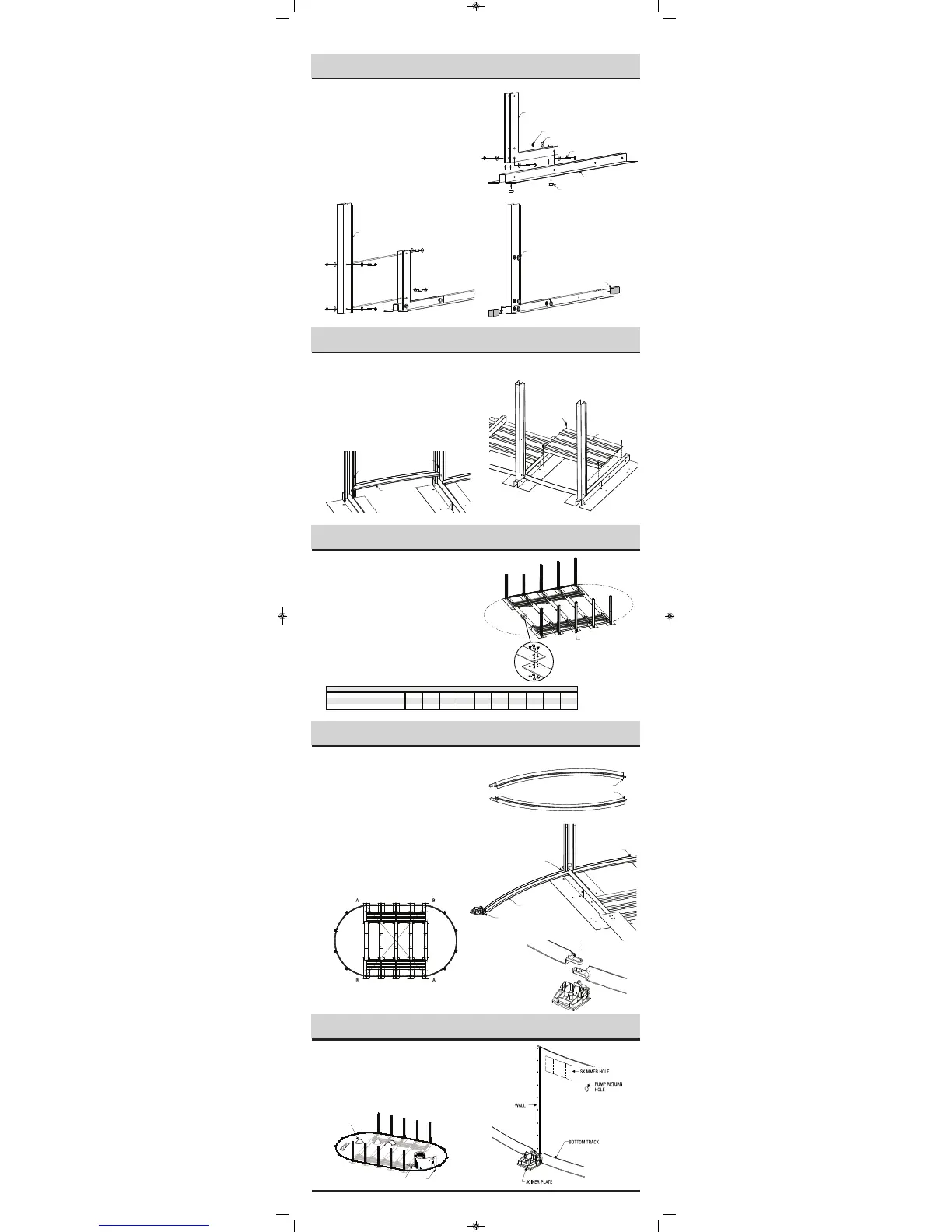
1) *+*13/--4231&3,/. To assemble, join splice brackets
(R) to the horizontal beam (Q) using the bolt 1/2 "X 3" X #13
(12.7 mm x 76.2 mm) (U), nuts (UU ) and washers (V). Remem-
b
er to insert a spacer (T) inside the beams aligned to each bolt.
2) *+*1 3/ --4231&3,/. Assemble the post using bolts
1/2" X 3" X #13 (12,7 mm X 76,2 mm) (U), nuts (UU) and
w
ashers (V). Remember to insert a spacer (T) and two washers
(
V) inside the beam aligned to each bolt.
3) *+*1 3/ --4231&3,/. Cover the bolt heads with bolt
caps (W) and insert the styrofoam caps (X) at both ends of foot
b
eam.
S
PLICE BRACKET
B
UTTRESS POST
1/2” BOLT CAP COVER
S
TYROFOAM CAP
W
ASHER 1/2”
N
UT 1/2”
F
OOT BEAM
S
POOL SLEEVE
B
OLT 1/2” X 3”
S
PLICE BRACKET
B
UTTRESS POST
1
/2” BOLT CAP COVER
S
TYROFOAM CAP
W
ASHER 1/2”
NUT 1/2”
F
OOT BEAM
SPOOL SLEEVE
BOLT 1/2” X 3”
SPLICE BRACKET
B
UTTRESS POST
1/2” BOLT CAP COVER
S
TYROFOAM CAP
W
ASHER 1/2”
N
UT 1/2”
F
OOT BEAM
S
POOL SLEEVE
B
OLT 1/2” X 3”
Illustration 4.1
Illustration 4.3
Illustration 4.2
1) Position the buttress pillars assembled in Step 4 on the patio
blocks in the trenches previously dug.
2
) *+*13/ --4231&3,/. Once the buttress pillars are
placed in the trenches, assemble the straight sections bottom
tracks (J) between the pillars by fixing them on the foot beams
using standard screws #14.
3) *+*13/--4231&3,/.Fix the pressure plates between
foot beams using 4 standard screws #14.
STANDARD SCREW #14
STANDARD SCREW #14
BOTTOM TRACK
STRAIGHT SECTION
5
STANDARD
S
CREW #14
PRESSURE PLATE
Illustration 5.2
Illustration 5.1
1) Study illustrations and chart carefully. You are now ready to
assemble the metallic tension straps. Refer to indications on the
chart for the exact number of tension straps and sections per
straps according to their respective pool size.
2) *+*13/--4231&3,/. If there is more than one metallic
strap per tension strap rows, assemble the straps together using 4
bolts and nuts (BB) 1/4" #20 X 5/8" (6,35 mm X 15,88 mm), tak-
ing care of placing the bolt head on top.
3) Attach the assembled tension straps to foot beams on both
sides, using 4 standard screws #14.
MODÈLE 10x16 10x21 13x18 13x23 15x20 15x26 15x31 18x33 18x38 18x44
NOMBRE DE BANDES TOTAL 3561061521212733
N
OMBRE DE RANGÉES À ASSEMBLER 35352577911
POOL SIZE 10x16 10x21 13x18 13x23 15x20 15x26 15x31 18x33 18x38 18x44
TENSION STRAPS QUANTITY (TOTAL) 3561061521212733
R
OWS TO ASSEMBLE 35352577911
STRAPS PER ROW 1122333333
Chart
$
6
Illustration 6.1
1) *+*13/--4231&3,/.2&.)Identify the 2 bottom
tracks A and B. These are the ends of straight sections.
2) *(3,/.2&.)1*+*13/--4231&3,/.
Place the short end of the bottom track on the foot beam of the
last pillar of the straight section and secure it with a standard
screw # 14. At the other end, place the first foot plate of the
round section.
3) /4.)2*(3,/.1*+*13/--4231&3,/.
Using the round section bottom tracks and the foot plates, start
with the first plate of the round section. Repeat this procedure
until the half circle is completed.
4) *+*13/--4231&3,/.
Before going to next step, make sure that the centre of the pool
is properly squared and metallic tension straps are stretched.
ROUND SECTION 1
S
T
BOTTOM TRACK (A)
ROUND SECTION 1
S
T
BOTTOM TRACK (B)
$
7
"
8
SAND
PLANKS
SUPPORT
BAR
SAND
BAR
SUPPORT
PLANKS
1
ST
TRACK (A)
ROUND SECTION
1
S
T
FOOT PLATE
ROUND SECTION
S
HORT END
BOTTOM TRACK
STRAIGHT SECTION
Illustration 7.4
Illustration 7.1
Illustration 7.2
Illustration 7.3
25x38-Trevi 222 OVALE_25-38-Trevi 209-218 OVALE.qxd 2010-03-01 14:32 Page 7
 Loading...