GEnERal InfoRMaTIon
This supplement requires the use of the IDWH Sensor
Kit PSRKIT22.
The IDWH Sensor kit should include the following parts:
2. Remove the thermostat’s sensing bulb from the
SMART drywell. Once the bulb is removed, coil the
thermostat capillary tube and bulb against the bot-
tom of the cover plate using care not to kink or dam-
age the capillary tubing.
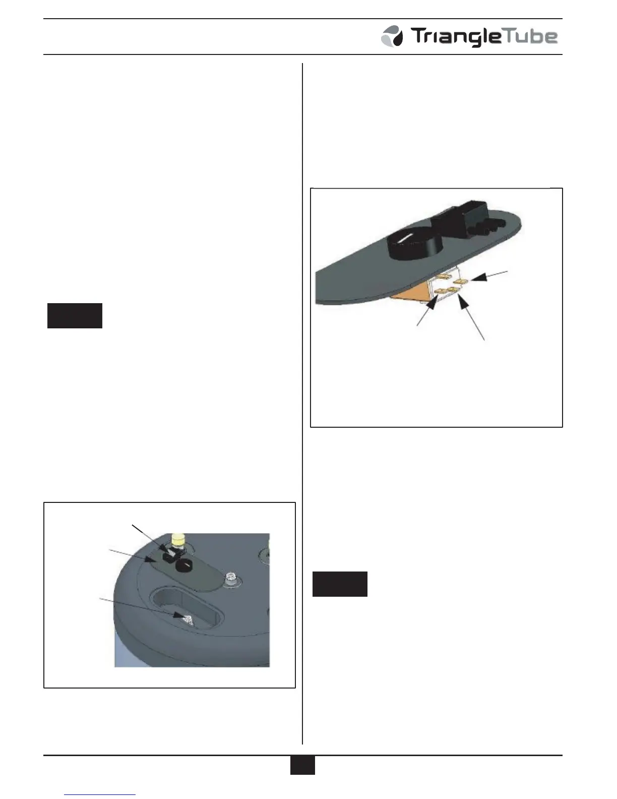
3. Disconnect the wire terminal connectors from C and
·
·
NTC Sensor with wire leads and connections
Terminal block tool
1 on the thermostat. There is no need to mark the
wires prior to disconnecting, as polarity of the con-
nections is not of importance. See Figure 2.
The use of this kit will allow the MCBA Control Module
of the Prestige boiler to control the domestic storage
temperature of the Indirect Water Heater, initiate the
burner function during domestic water draw and protect
the tank from freezing.
InSTallaTIon PRocEduRE
WARNING
1
Electrical Shock Hazard. Turn power off to the
Prestige boiler before proceeding with the kit instal-
lation. failure to comply could result in severe per-
sonal injury, death or substantial property damage.
C
Disconnect Existing
Wire Connections from
Thermostat Terminals
Insertion of the nTc Sensor
Fig. 2: Thermostat Cover Plate Assembly
1. Remove the thermostat cover plate from the
SMART lid. A flat blade screwdriver may be
required to pry the cover plate up from the lid. Use
care not to damage the cover plate or the SMART
top lid. See Figure 1.
Snap-Set
Connector
Thermostat
Cover Plate
4. Connect the NTC sensor terminal connectors to the
wires previously connected to C & 1. This proce-
dure should now wire the NTC sensor to the Snap-
Set connector mounted on the thermostat cover
plate.
5. Insert the NTC sensor into the drywell. The recom-
mended depth placement of the NTC sensor should
be from the fullest length of the sensor wires with a
placement of the bulb a minimum 6 inches from the
bottom of the drywell.
NOTICE
Drywell
actual placement of the nTc sensing will affect the
response of the sensor and it’s call for heat to the
Prestige during a draw of domestic hot water. a
high placement position will result in a slower
Fig. 1:
Smart Thermostat Cover Plate Access
2
response, where as a lower placement position will
create a quicker response.
6. Snap the thermostat cover plate back into position
on the SMART top lid. Ensure the mounting pins of
the cover plate are fully inserted into the top lid.

 Loading...


