PRESTIGE Solo 60, 110, 175 and 250
HX Field Replacement
Kit
6
Removal of Water Connections
1. Remove condensate trap and cabinet gasket
from the boiler. Do not discard, as they will be
reused. Cut serrated washer on polypropylene
condensate pan to remove retaining nut.
2. Using a pipe or adjustable wrench, loosen the
brass union nuts located on the internal return
and supply connections of the heat exchanger.
3. Removal of the supply pipe requires the removal
of the piping support flange and the 2 mounting
screws (if present) along with the relief valve /
air vent piping. Do not discard the piping sup-
port flange and mounting screws. Once the
boiler supply and return piping are disconnect-
ed, discard the existing boiler piping gaskets.
4. Cut tie strap holding the heat exchanger in place
at the bottom of the unit (if present).
Removal of Heat Exchanger
Obtain assistance in lifting the heat exchanger
from the cabinet as 2 people will be required.
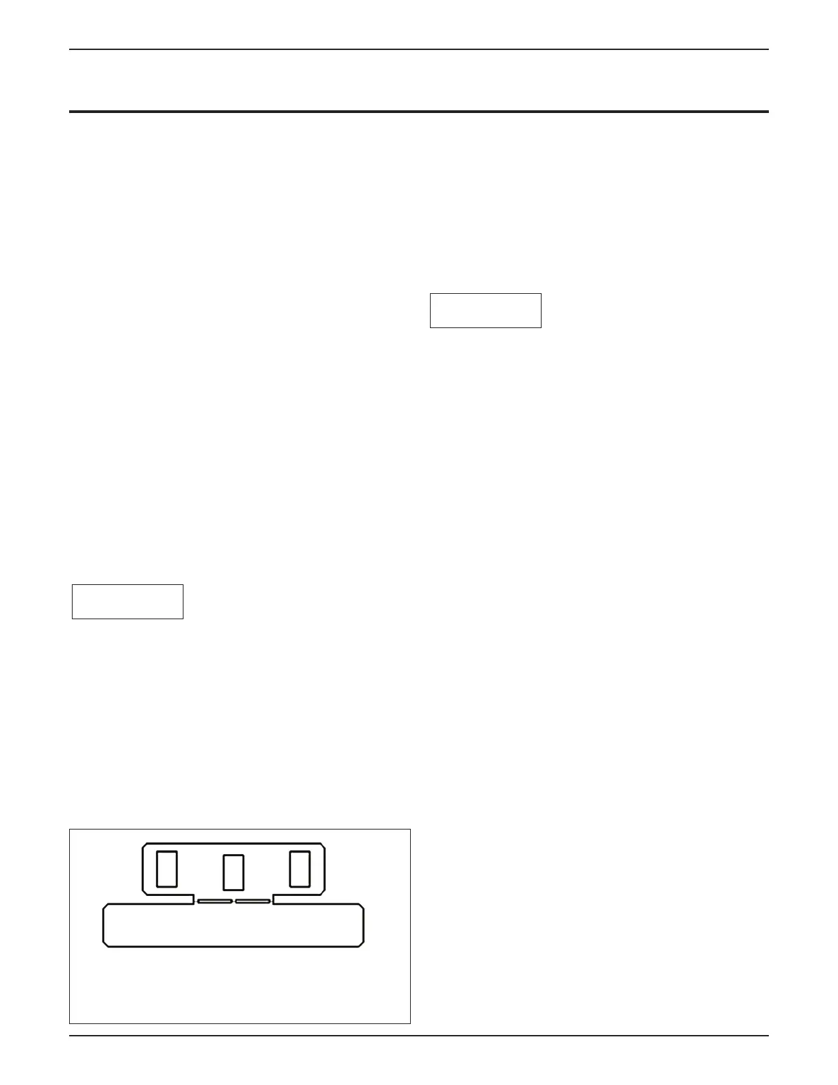
1. Remove the sheet metal “anti-bounce” bracket
insert (if present) from the upper mounting
brackets located behind the heat exchanger
(Fig. 8). This clip is used to avoid vertical
motion of the heat exchanger during transport
and is not required to be installed with the
replacement heat exchanger.
2. Lift the heat exchanger about 4” to 6” to disen-
gage from the rear jacket panel and clear the
condensate tube from the bottom panel. Tilt
heat exchanger forward from the top and care-
fully rotate it forward in order to remove from
the boiler cabinet.
Preparation of New Heat Exchanger
Do not damage or throw away shipping box,
foam packs, and HX Tracking Form as all these
items are used to return the old heat exchanger,
if required for warranty evaluation.
1. Carefully open and unpack the PARTS BOX
from its shipping carton.
2 . Carefully remove heat exchanger from shipping
box. Do not discard packing materials, as the
shipping box should be reused to return the old
heat exchanger back to Triangle Tube if
required for warranty consideration.
3. Check new heat exchanger for any damage.
Check position of the flue gasket in the new heat
exchanger.
4. Install new temperature sensors with O-ring gas-
kets in return and supply sensing locations.
5. Install new temperature sensor with O-ring gas-
ket in flue sensing location (PSRKIT01 &
PSRKIT76 only)
6. Install the new igniter gasket and igniter in the
burner plate using 2 screws provided. Some heat
exchanger kits include two different style ignit-
ers. Install the same style igniter as originally
installed in the boiler. Tighten screws evenly.
See Table 2, page 14 for torque specifications.
NOTICE
NOTICE
Fig. 8: Heat Exchanger “Anti-bounce”
Bracket
 Loading...


