Date: April 14, 2020 Doc No: PS-M-0871 Ver: B Page 13 of 21
144 pcs
Back sheet-
Glass
Framed
Module
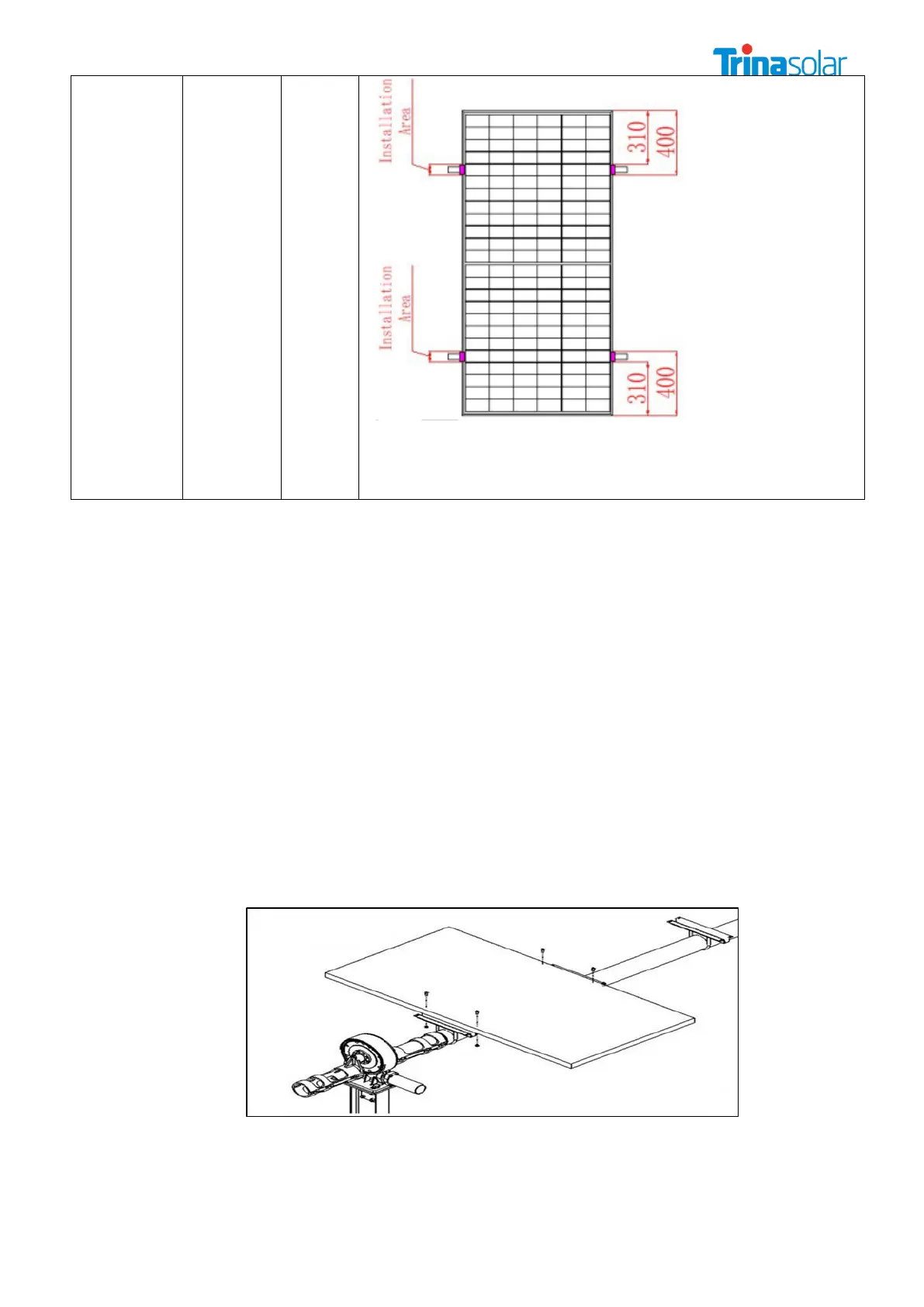
*NOTE: The above-described distance is from the module edge to the middle
of the clamp
*NOTE: Need two support rails below the PV module to make sure the
Mechanical load.
*NOTE: The actual load is + 5400Pa/-2400Pa
C. Mounting with Single-axis Tracking System(4-φ7*10mm mounting holes)
Modules can be attached using the mounting holes on the back of the module frame, by fixing
the module to the support rails with bolts. The mounting details are shown in the following figures.
The frame of each module has 4-φ7*10mm mounting holes, ideally placed to optimize the load
handling capability, to secure the modules to supporting structure. 4 installation holes of φ7*10
mm are used for Single-axis tracking system installation, as shown in Figure 2
To maximize mounting longevity, Trina Solar strongly recommends the use of corrosion proof
(stainless steel) attachment hardware.
Secure the module in each mounting location with an M6 bolt and a flat washer, spring washer
and nut.
If a different bolt similar to M6 is used, they need to be tightened to a torque of 16N.m.(140lbf.in).
Flat stainless steel gaskets with a minimum thickness of 1.5mm and an external diameter of 16-
20mm (0.63-0.79 inches) shall be used in all parts of the components connected to the Single-
axis tracking system.
Mechanical Load Pressure under this method: 30 lbs.ft
2
max from the front side & 30 lbs.ft
2
max
from the rear according to UL1703.