SAVE THIS OWNER’S MANUAL ADDENDUM.
It contains important instructions and warnings that should be followed
during the wallmount installation of Tripp Lite PowerVerter Systems.
Wallmount Warnings
• This wallmount procedure has not been tested by Underwriter
Laboratories and is not UL approved.
• If you install your PowerVerter in a vehicle, mount it on a horizontal
surface, not a vertical surface.
• Mount your PowerVerter indoors, away from excess moisture or
heat, dust or direct sunlight.
• Leave adequate space around all sides of the PowerVerter for
proper ventilation.The more power connected equipment draws,
the more heat will be generated by the PowerVerter.
• Do not install the PowerVerter near magnetic data storage media,
as this may result in data corruption.
Wallmount Procedure
User must supply all fasteners and brackets and verify their suitability
for use with the intended mounting surface.Turn your PowerVerter and
connected equipment OFF before mounting.
Wallmounting for the PV 500FC, PV 1000FC or APS 512
(See Diagram 1)
• Install four 5mm (#8) fasteners (A) into a rigid vertical surface using
the measurements in the diagram. Leave the heads of the fasteners
raised slightly above the surface in order to engage the keyhole
slots molded into the bottom of the PowerVerter's feet.
• Place keyhole slots in the PowerVerter's four feet over the four fas-
teners and slide the PowerVerter forward or down to secure it. The
control panel should face up. Install an "L"-shaped bracket (B) as
shown to secure the PowerVerter.
Wallmounting for the PV 2000FC, PV 2400FC, APS 1012, APS 1024,
APS 2012, APS 2424, APS 2448 or APS 3636
(See Diagram 2)
• Install two 8 mm (1/4 in.) fasteners (A) into a rigid vertical surface
using the measurements in the diagram. Leave the heads of
fasteners raised slightly above the surface in order to engage
the slots in the PowerVerter's feet.
• Slide PowerVerter up to fully engage the fasteners in the
PowerVerter's front feet.The PowerVerter’s control panel should
face up. Install two 8 mm (1/4 in.) fasteners (B) into the surface,
through the slots in the PowerVerter's two unsecured bottom feet.
Tighten the screws to permanently hold the PowerVerter in position.
Installing a Drip Guard
(See Diagram 1 or 2)
• A drip guard is recommended when wallmounting all PowerVerter
models. Leave a space between the PowerVerter and the guard to
allow for proper ventilation to the inverter. Use sheet metal screws
(C) to mount a sheet metal splash guard (D) measuring as shown
4" to 6" above the control panel of the PowerVerter. User must sup-
ply drip guard, screws and spacers.
1111 W. 35th Street • Chicago, IL 60609 USA
Customer Support: (773) 869-1234
www.tripplite.com
Owner's Manual Addendum
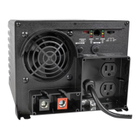
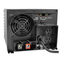
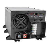
PowerVerter
Wallmount Instructions
For PowerVerter Plus and
PowerVerter APS Models
Copyright © 2001 Tripp Lite. All rights reserved.
PowerVerter
®
is a registered trademark of Tripp Lite.
Diagram 1
Mounting for PV 500FC, PV 1000FC and APS 512
Diagram 2
Mounting for
PV 2000FC, PV 2400FC, APS 1012, APS 1024,
APS 2012, APS 2424, APS 2448, APS 3636