Do you have a question about the Tripp Lite PowerVerter APS 612 and is the answer not in the manual?
Explains how advanced circuitry provides efficient DC-to-AC conversion, minimizing energy loss for longer equipment operation.
Details the APS's ability to automatically protect itself and connected batteries from damage due to overload.
Describes the indicator lights that provide constant information on battery charge, fault conditions, and APS operation.
Covers user-configurable switches for voltage selection, battery charging optimization, and remote control setup.
Explains the three-stage charging profile (Bulk, Absorption, Float) for faster battery recharge and protection.
Details how frequency control ensures proper operation of AC line frequency-dependent devices like computers and VCRs.
Highlights the silicone conformal coating that safeguards internal circuit boards against moisture.
Provides essential warnings regarding the proper indoor installation of the APS, emphasizing ventilation and avoiding moisture.
Outlines critical safety precautions for connecting batteries, including ventilation, polarity, and preventing short circuits.
Details warnings about altering cords, using proper grounding, and avoiding connecting other devices to the APS output.
Covers safety guidelines during operation, including not opening the unit, handling internal voltages, and avoiding arcing.
Explains the use of four DIP switches on the front panel to configure battery type and voltage switching points.
Instructions on setting DIP Switch #1 to match the connected battery type (Gel Cell or Wet Cell) to prevent damage.
Guidance on setting DIP Switch #2 for the high AC voltage threshold that triggers a switch to battery power.
Instructions for setting DIP Switches #3 and #4 for the low AC voltage threshold that triggers a switch to battery power.
Guidance on choosing appropriate deep-cycle batteries (Wet-Cell or Gel-Cell) for optimal APS performance and longevity.
Steps to calculate the required battery amp-hour capacity based on equipment wattage and desired backup time.
Details the requirement for connecting APS systems to a grounded wiring system, bonding the negative conductor to ground.
Instructions for connecting the APS line cord to a properly grounded 120V, 60 Hz outlet with adequate circuit protection.
Guidance on plugging connected equipment into the unit's AC receptacles for power delivery.
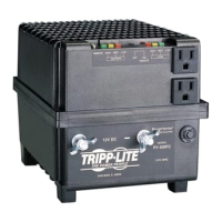
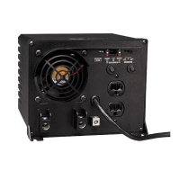
Explains the functions of the Operating Mode switch: AUTO/REMOTE, CHARGE ONLY, and OFF for various operational scenarios.
Details the function of the Operating Mode switch, allowing selection between AUTO/REMOTE, OFF, and CHARGE ONLY modes.
Explains the role of DIP switches in setting battery type and voltage points for optimal APS performance.
Describes the green 'LINE' indicator, showing utility power status and APS mode (charging or active).
Explains the yellow 'INV' indicator, which lights up when the unit is supplying battery-powered AC.
Details the red 'LOAD' indicator, alerting to high load conditions or potential overload and overheating.
Explains the 'BATTERY HI/MED/LO' lights that indicate approximate battery charge level and voltage status.
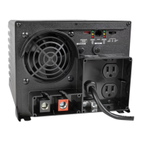
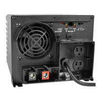
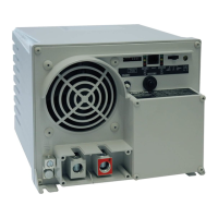
Information on the DC power terminals for wiring connection to the battery bank, referencing the Battery Connection section.
Specifies the NEMA 5-15P cord for connecting to a 120V, 60 Hz AC utility outlet, emphasizing not plugging into receptacles.
Details the NEMA 5-15R AC receptacles for connecting equipment that would normally use a utility outlet.
Explains the function of input and output circuit breakers for protecting the APS against overloads.
Information about the RJ45 receptacle for connecting an optional remote module for extended control and monitoring.
Describes the use of mounting flanges and slots for securely mounting the APS to a sturdy, horizontal surface.
Provides guidance on keeping the APS dry and periodically checking and tightening all connections for optimal performance.
Instructions for returning the APS to Tripp Lite for service, including packing, documentation, and proof of purchase.
| Input Voltage | 12V DC |
|---|---|
| Output Voltage | 120V AC |
| Output Frequency | 60 Hz |
| Output Waveform | Modified Sine Wave |
| Output Power | 600W |
| Surge Power | 1200W |
| Protections | Overload, Short Circuit, Over Temperature |
| Operating Temperature | 32°F to 104°F (0°C to 40°C) |
| Efficiency | 90% (full load) |
| Transfer Time | Not applicable (Inverter only) |