6
Standard 1 x 2 Extender Kit Installation
1
MakesurealldevicesbeingconnectedarepoweredOFF.
2
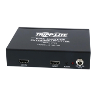
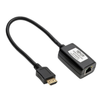
ConnecttheHDMIsourcetotheINPUT port on the transmitter unit
usingaTrippLiteP568-SeriesHigh-SpeedHDMICable.
3
Optional: Connect a monitor to the LOCAL port on the transmitter
unitusingaTrippLiteP568-SeriesHigh-SpeedHDMICable.
4
Connecttheexternalpowersupplytothetransmitterunitandplugthe
transmitterunitintoaTrippLiteSurgeSuppressor,PowerDistribution
Unit(PDU),orUninterruptiblePowerSupply(UPS).ThegreenRJ45LED
illuminatestoindicatethattheunitisreceivingpowerfromtheexternal
power supply.
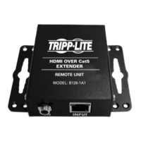
5
UsingCat5e/6cable,connecttheRJ45portonthetransmitterunit
marked OUTPUTtotheRJ45portonthereceiverunitmarkedINPUT.
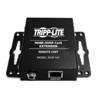
6
Connect theexternal power supplyto the receiver unitand plug the
receiverunitintoaTrippLiteSurgeSuppressor,PowerDistributionUnit
(PDU), or Uninterruptible Power Supply (UPS). The green RJ45 LED
illuminatestoindicatethattheunitisreceivingpowerfromtheexternal
power supply.
7
Connect a monitor to the OUTPUT 1 port on the receiver unit using a
TrippLiteP568-SeriesHigh-SpeedHDMIcable.
8
Repeat step 7 for the OUTPUT 2 port on the receiver unit.
9
Turnonthepowertotheconnecteddevices.TheorangeRJ45LED’s
on the transmitter and receiver units illuminate to indicate that a
signalisbeingreceivedfromtheHDMIsource.Thevideoimagewill
now be displayed on the connected monitors.
10
Ifnecessary,usetheEqualizationcontrolonthereceiverunittoadjust
the video image. Note: An improper Equalization setting can cause
the monitor not to display an image at all. Try each setting until an
acceptable image is displayed.
13-08-043 93-32D0.indd 6 8/28/2013 2:17:38 PM

 Loading...