Do you have a question about the Tripp Lite SmartOnline SU20KX and is the answer not in the manual?
Highlights key features of the SmartOnline 3-Phase UPS Systems for various applications.
Details environmental and physical placement requirements for safe UPS installation.
Outlines critical electrical connection safety precautions and hazards.
Specific safety guidelines for handling and maintaining UPS batteries.
Safety precautions related to electrical wiring practices for the UPS.
Explains the LEDs, LCD screen, and buttons on the UPS control panel.
Identifies and describes the physical ports and components on the UPS panels.
Steps for preparing the installation site and confirming the UPS system.
Procedures for safely unpacking the UPS system from its shipping container.
Guidelines for positioning the UPS system in its final installation location.
Visual guides for connecting internal battery strings to the UPS.
Step-by-step instructions for connecting internal UPS batteries.
Critical safety warnings for all UPS wiring procedures.
Steps for preparing cables and understanding wiring diagrams.
Diagram illustrating the UPS system's terminal block connections.
Diagrams for wiring external battery cabinets to the UPS.
Table detailing electrical specifications and cable requirements for UPS models.
Instructions for wiring external battery cabinets to the UPS.
Procedure for connecting AC input and output for a single UPS.
Wiring for parallel UPS systems using a single input source.
Wiring for parallel UPS systems using dual input sources.
Describes the UPS operation in normal, double-conversion mode.
Explains UPS operation during a power outage using battery power.
Details UPS operation when switching to bypass due to faults.
Procedure for manually bypassing the UPS for maintenance.
Describes online operation for parallel UPS configurations.
Explains battery backup for parallel UPS systems.
Details bypass operation for parallel UPS systems.
Procedure for manual bypass in parallel UPS configurations.
Describes the redundant UPS acting as a bypass source.
Identifies control panel elements and circuit breaker locations.
Pre-startup checks for single UPS system installation.
Step-by-step guide to starting up a single UPS system.
Procedure for starting the UPS using battery power.
Steps to place a single UPS into manual bypass mode.
Steps to safely shut down a single UPS system.
Pre-startup checks for parallel UPS system installation.
Step-by-step guide to starting up parallel UPS systems.
Steps to safely shut down parallel UPS systems.
Procedure to manually bypass parallel UPS systems.
Procedure to return parallel UPS systems to normal mode.
Labeled diagram of the UPS control panel components.
Visual representation of the UPS LCD menu structure.
Description of the standard UPS status screen after self-test.
Explains various operational status messages shown on the UPS LCD.
Overview of accessing and navigating the UPS main menu.
Accessing and logging into the UPS system setup menu.
Configuring bypass voltage and frequency settings.
Adjusting output voltage, frequency, ECO mode, and redundancy.
Configuring battery type, strings, dates, and test duration.
Setting the charger current for the UPS batteries.
Configuring parallel group and ID settings for UPS systems.
Setting up battery tests, buzzer, and LED tests.
Configuring local settings like date, time, and language.
Accessing firmware version, statistics, event logs, and advanced options.
Overview of the UPS system's communication ports.
Information on installing the SNMPWEBCARD for remote management.
Details on input dry contact signals for commands and monitoring.
Diagram for connecting the EPO circuit for remote shutdown.
Diagram for auxiliary dry contact inputs.
Inputs for monitoring external battery cabinet temperatures.
Input for external battery cabinet status signals.
Explains the UPS's dry contact output messages and descriptions.
Wiring diagram for the UPS dry contact outputs.
Wiring diagram for the RS-232 serial port.
Details on connecting UPS systems in parallel.
Detailed technical specifications for UPS models.
Table showing floor loading weights for UPS systems.
Table showing floor loading weights for battery packs.
Guidelines for storing the UPS system properly.
Procedures and information for obtaining product service.
Details the product's limited warranty terms and conditions.
| Frequency | 50/60 Hz |
|---|---|
| Transfer Time | 0 ms |
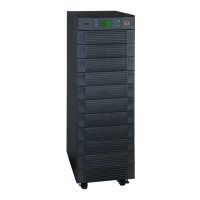
| Form Factor | Tower |
| Input Connection Type | Hardwire |
| Power Capacity | 20 kVA |
| Input Voltage | 208; 220; 230; 240 |
| Output Voltage | 208; 220; 230; 240 |
| Topology | Double Conversion Online |
| Battery Type | Sealed Lead Acid (SLA) |
| Runtime | Varies based on load |
| Battery Recharge Time | 4 hours to 90% capacity |
| Audible Noise | < 60 dB at 1 meter |
| Operating Temperature | 0°C to 40°C (32°F to 104°F) |
| Humidity | 0 to 95% (non-condensing) |
| Communications | USB, RS-232 |
| Warranty | 2-year limited warranty |