Do you have a question about the Tripp Lite SmartOnline SU40K and is the answer not in the manual?
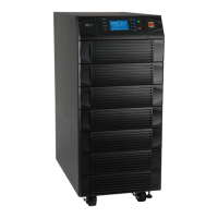
Details on advanced features of the SmartOnline 3-Phase UPS Systems.
Guidance on proper placement and environmental conditions for UPS installation.
Critical safety precautions for electrical connections and system usage.
Safety precautions and handling guidelines for UPS batteries.
Precautions and best practices for UPS system wiring.
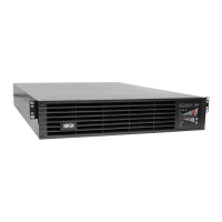
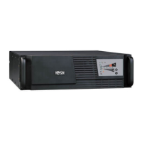
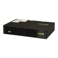
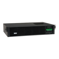
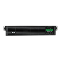
Description of control panel LEDs, LCD screen, and buttons.
Steps for preparing the installation site and the UPS unit.
Procedure for safely unpacking the UPS system from its shipping container.
Guidelines for positioning the UPS system in its final location.
Diagrams illustrating internal battery wiring for the SU40K model.
Step-by-step instructions for connecting internal UPS batteries.
Critical warnings and safety precautions for UPS system wiring.
Steps to prepare for wiring the UPS system and external battery cabinet.
Diagram showing UPS system terminal block connections for input, output, and battery.
Wiring diagrams for connecting external battery cabinets.
Table detailing electrical specifications and required cable sizes for UPS models.
Procedure for wiring external battery cabinets to the UPS system.
Instructions for AC input and output wiring for a single UPS unit.
Wiring procedures for parallel UPS systems with a single input.
Description of the UPS system operating in online (normal) dual conversion mode.
Explanation of the UPS system operating on battery power during an outage.
How the UPS system switches to bypass mode due to internal issues.
Procedure for manually bypassing the UPS for maintenance or repair.
Parallel operation in online mode, with load sharing between UPS units.
Parallel operation in battery backup mode, load shared by multiple UPS units.
Parallel operation in auto bypass mode due to internal UPS issues.
Manual bypass operation for parallel UPS systems for maintenance.
Diagrams of the control panel and circuit breakers for UPS operation.
Pre-start-up checks for single UPS system installation.
Steps to perform a normal start-up of a single UPS system.
Procedure for starting a single UPS system using battery power.
Instructions for placing a single UPS system into manual bypass mode.
Steps to safely shut down a single UPS system.
Final steps for safely shutting down a single UPS system.
Pre-start-up checks for parallel UPS system installation.
Steps to start up parallel UPS systems.
Continuing steps for starting up parallel UPS systems.
Steps to safely shut down parallel UPS systems.
Final steps for safely shutting down parallel UPS systems.
Procedure for placing parallel UPS systems into manual bypass mode.
Continuing procedure for manual bypass in parallel UPS systems.
Steps to return parallel UPS systems from manual bypass to online mode.
Diagram identifying components of the UPS control panel.
Overview of the menu structure and navigation flow on the UPS display.
Description of the default screen shown after UPS self-test.
Explanation of various status messages and system operating diagrams.
Further explanation of status messages and system operating diagrams.
Accessing and navigating the UPS main menu options.
Viewing real-time UPS system measurements and data.
Accessing and navigating the UPS system setup menu with password.
Configuring bypass voltage and frequency settings for the UPS.
Continued configuration of bypass voltage and frequency.
Configuring output voltage, frequency, and modes for the UPS.
Continued configuration of output parameters like frequency and ECO mode.
Setting battery parameters for accurate runtime estimates.
Further settings for battery type, charger current, and auto test.
Configuring local settings like date, time, password, and language.
Continued configuration of audible alarms, display contrast, and serial port.
Accessing maintenance functions like statistics and event logs.
Viewing and resetting UPS operating statistics.
Viewing and erasing the UPS system's event log.
Performing manual tests and configurations on the UPS.
Instructions for upgrading UPS system firmware by qualified personnel.
Accessing information on serial number, firmware version, and DC bus voltage.
Overview of available communication ports and interfaces on the UPS.
Information about installing and using the SNMPWEBCARD accessory.
Details on input dry contact signals for commands and monitoring.
Circuit diagram for connecting the EPO input for remote shutdown.
Circuit diagram for auxiliary dry contact inputs.
Connection details for external battery cabinet temperature monitoring.
Connection details for external battery cabinet status signals.
Details on default and optional messages for dry contact outputs.
Circuit diagram for the UPS system's dry contact outputs.
Circuit diagram for connecting the UPS via RS-232 serial port.
Information on connecting UPS systems for parallel redundancy.
Detailed technical specifications for all UPS models.
Floor loading requirements for UPS system installation.
Floor loading requirements for external battery packs.
Guidelines for storing the UPS system to maintain its condition.
Information on available service programs and customer support.
Details of the product's warranty terms and conditions.
Instructions for registering the product warranty online.
| Brand | Tripp Lite |
|---|---|
| Model | SmartOnline SU40K |
| Category | UPS |
| Language | English |