14 15
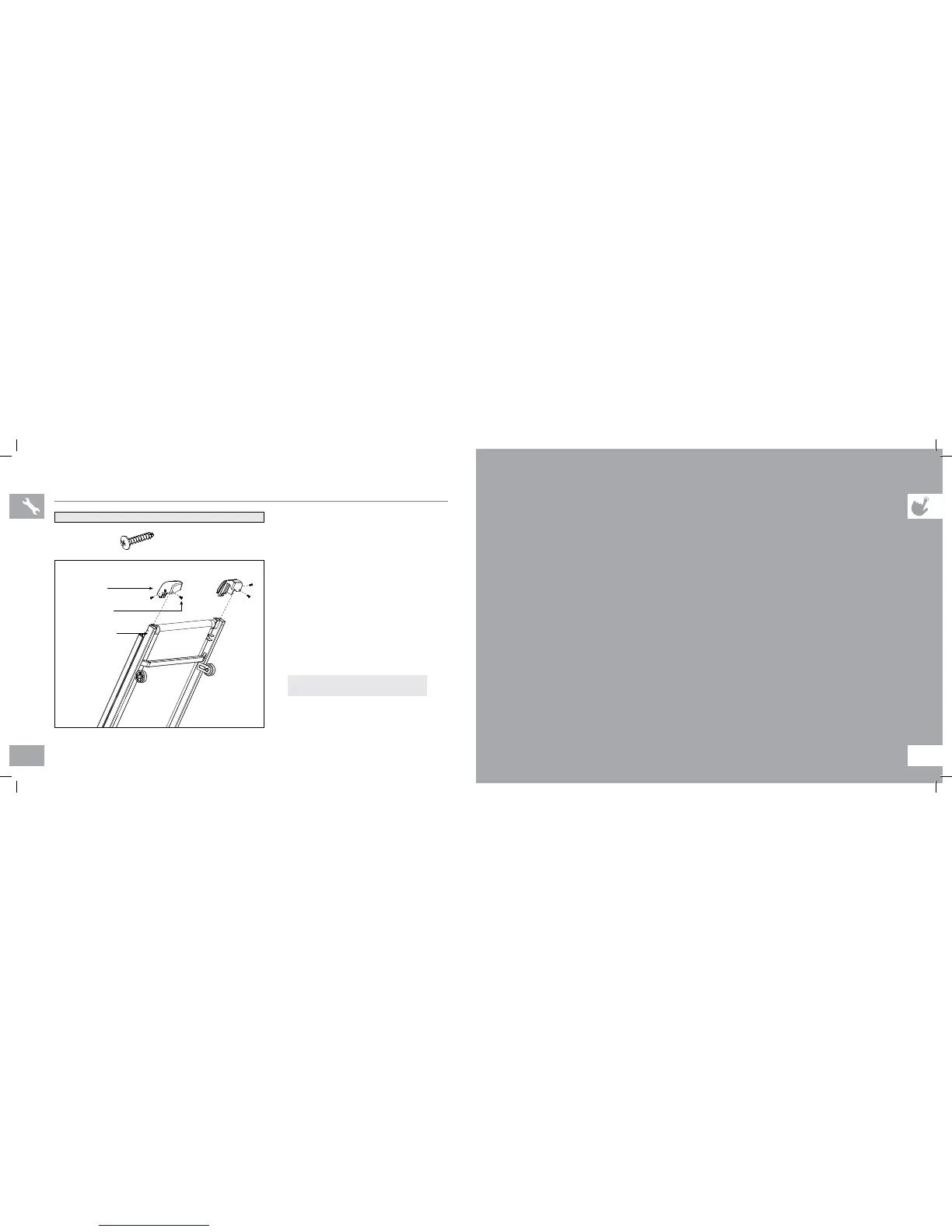
ASSEMBLY STEP 4
A Open hardware bag 4.
NOTE: lock latch must be securely engaged
before proceeding with assembly. (See folding
instructions in TREADMILL GUIDE.)
B Attach the right end cap using 2 screws
(h). Repeat on the other side.
C Connect power cord to a power outlet. The
ON/OFF switch is located next to the power
cord. Flip this switch to the ‘ON’ position. You
will hear a beep and the console will turn on.
D Before the first use, lubricate the treadmill
deck by following the instructions in the
MAINTENANCE section in the TREADMILL
GUIDE.
SCREW (H)
12 mm
Qty: 4
HARDWARE BAG 4 CONTENTS :
END CAPS
SCREWS (H)
MAIN FRAME
YOU ARE FINISHED!
TREADMILL OPERATION
This section explains how to use your treadmill’s console and programming. The BASIC OPERATION section in the
TREADMILL GUIDE has instructions for the following:
• LOCATION OF THE TREADMILL
• USING THE SAFETY KEY
• FOLDING THE TREADMILL
• MOVING THE TREADMILL
• LEVELING THE TREADMILL
• TENSIONING THE RUNNING BELT
• CENTERING THE RUNNING BELT
• USING THE HEART RATE FUNCTION
400T-OM-rev1_1.indd 14-15 10/29/10 1:44 PM