ELECTRICAL SYSTEM
Switch on the headlamps and adjust the lamps, if necessary, until the
centre of each circle of light coincides with the centre of its respective cross.
If adjustment is necessary, proceed as follows :
Withdraw the front rim as shown on Fig. 41.
Remove the
dust-excluding rubber.
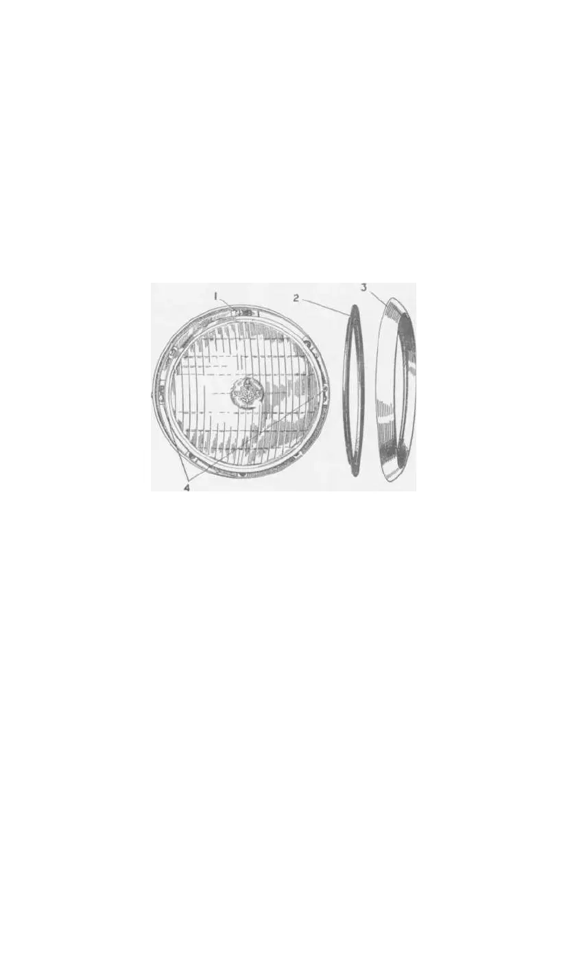
This will reveal three screws (see Fig. 42),
which can be adjusted to align the reflector correctly.
When the
correct alignment has been obtained, replace the rubber and rim.
It is advisable to start adjustment with each screw screwed out half-way ;
this will ensure correct fitting of the rim when assembled.
1.
Vertical adjusting screw.
2.
Dust excluding rubber.
3.
Front rim.
4.
Horizontal adjusting screws.
Fig.
42.
Adjusting headlamp alignment.
Parking Lamps (Front) and Direction Indicator Flashing Lamps
(front and rear)
To remove bulb, peel back the rubber ring and remove rim, then the bulb
can be withdrawn.
When replacing rim, first slip the edge over the two
small lugs, then peel back rubber as rim is fitted. Ensure that the rubber
is located correctly over the rim edge, otherwise vibration may cause the
rim to become detached.
Tail and Stop Lamps
To gain access to the bulb, remove the cover, which is secured by two
screws.
Number Plate Lamp
To gain access to the bulb, remove the securing screw and withdraw
the cover.
4 7
SPORTS CAR