Do you have a question about the Tronair 02-7856-0100 and is the answer not in the manual?
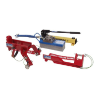
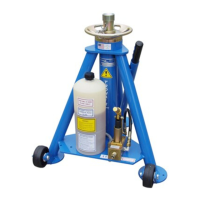
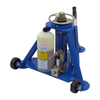
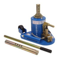
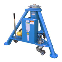
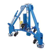
This manual describes the Tronair 5 Ton (4.5 Metric Ton) Single Stage Jack, available in several models: 02-7856-0100 (Standard), 02A7856-0100 (with Air Pump Option), 02B7856-0100 (with Air Pump Option & Spring Loaded Casters), and 02C7856-0100 (with Spring Loaded Casters).
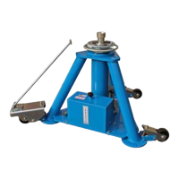
The Tronair 5 Ton Single Stage Jack is designed to lift an aircraft by its fuselage and/or main wing. It utilizes hydraulic jacks arranged by position and quantity to provide proper balance, ensuring that the aircraft jack pad, whose maximum load on any one jack does not exceed the rated capacity of the jack, is properly supported. The jacks are not intended for metal forming, metal working, or any purpose other than that stated above.
The jack has a rated capacity of 10,000 lbs (4,536 kg). Its minimum closed height is 30 inches (76.2 cm), and its mechanical extension is 12 inches (30.48 cm). The hydraulic extension is 22 inches (55.88 cm), resulting in a maximum height obtainable of 64 inches (162.56 cm). The jack weighs 105 lbs (47.63 kg). The pressure relief setting is 1,950 + 195/-0 psig (13.4 + 1.3/-0 bar). The noise level is 84 dB(A) at a distance of 120 inches (304.8 cm) at an inlet pressure of 100 psi (6.9 bars).
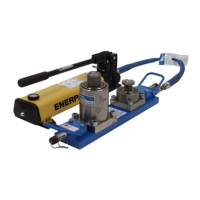
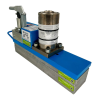
For models with the air pump option, the air drive system requires a minimum pressure of 25 psi (1.72 bar) to actuate the air motor, and a maximum of 125 psi (8.6 bar) for safe, efficient, and long-term reliable operation. The maximum air drive pressure is 125 psi (8.6 bar). The air pump models are equipped with a 1/3 HP pump series (M, MS, MCPV, MDSTV, 29723 models) from Haskel. The hydraulic fluid used is MIL-H-5606 or MIL-H-83282 Hydraulic Fluids.
Safety Information: The manual emphasizes several safety precautions. Ram locknuts are user-operated safety devices, and failure to utilize them can result in personal injury or death. Users must never place hands on top of jack near ram locknuts while lowering the jack, and pinch points exist between the top of the jack and threads on the ram. Always wear safety glasses.
When operating, users must never put hands between the aircraft and the jack pad, especially after the aircraft has been lowered, as struts may have hung up. It is crucial to never align the jack under an aircraft by pounding on the jack legs, as dented legs may lead to jack collapse. The ram locknut(s) must always be lowered after the jack is under load, and the ram nut(s) must be seated fully after jacking. Always raise and lower jacks simultaneously so that the aircraft remains level. Always use a tail or nose stand, as applicable, for additional stability.
Operating Procedures: The user must work in accordance with the Operator Manual and/or Technical Manuals. Personnel must work under the raised load until it is secured by suitable means, such as a ram locknut. The employer of the operator must provide all necessary training and give information about pumping and translating forces. Operations should be conducted between -20° C and 50°C/-4° F and 122° F.
To raise the aircraft, place the jack on a hard, level surface. Raise the mechanical extension as close to the aircraft jack pad as possible. The locking pin must be placed in the ram protection ring groove and fully through the mechanical extension. The locking pin washer and ball lock must be placed outside the ram protection ring.
Jack Instructions:
To lower the aircraft, lower all jacks simultaneously. If the ram locking nut(s) is tight, raise the jack slightly to release the nut(s). Loosen the pump release valve slightly to slowly lower the aircraft. Raise the locking nut(s) as the jack ram(s) lowers. When using the jack during washing operations, completely cover the top of the jack ram seal.
General Maintenance: All maintenance and/or repair work should be done using good workmanship practices and proper tools. The work area should be clean and free of dirt. When O-rings and backup rings are removed, every effort should be made to avoid contact of tools with the critical surfaces of parts. Surface deformities could cause degradation of seals and failure. It is good practice to replace both O-rings and backup rings once removed. Cut and damaged O-rings normally result in fluid leakage. If the cylinder bore is found to be rusty, it may be honed to a maximum diameter of 2.629 inches (66.78 mm) and a surface finish of 16 micro inches. If pitting in the bore cannot be removed by this process, the jack cylinder must be replaced before the jack can be returned to service. At this time, flush old hydraulic fluid and dirt from the overall system and replenish with new, clean hydraulic fluid. When refilling the hydraulic system, the characteristics of the hydraulic fluid used in the jack and the level of the hydraulic fluid must be observed. Jacks must be maintained and repaired by qualified persons. No modifications should be carried out which adversely affect the compliance of the jack with draft standard prEN 1454-1994.
Maintenance Schedule:
Storage/Low Usage: If the jack is unused for 90 days, raise the ram to full hydraulic extension, spray the ram with DoALL RPM, LPS, or equivalent water repellent, BUNA N compatible lubricant.
Servicing Jack: To disassemble the jack:
Removing and Servicing Pump: If the pump is found faulty, call the factory for replacement or replace seals as follows:
Jack Function Load Test: If a function load test is required:
Trouble Shooting: The manual provides a troubleshooting guide for common issues: