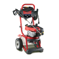
Section 3: Assembly
Z Secure tray to handle with self tapping screws using a
#2 phillips screwdriver, Ensure screws are tight but not
crushing the plastic accessory tray.
3. Place handle assembly onto handle supports connected
to main unit. Hake sure holes in handle align with holes
on handle supports (Figure 2).
7. Pinch chemical hose and slide it into metaHchip as
shown in Figure 5.
Handle
Align Holes/--_
NOTE: It may be necessary to move the handle supports
from side to side in order to align the handle so it will slide
over the handle supports.
4. [nsert"U' bolt through hole on right side of handle
(viewing from handle side of unit) and attach plastic
knob.Tighten knob by hand (Figure 3).
5.
6.
G
Insert carriage bok through left side hole from outside
of unit and attach a plastic [<nob from inside of unit
(viewing unit from the handle side).Tighten by hand
(Figure 3).
Insert "J" hook into second from left slot in accessory
tray (Figure 4).
8.
Tilt unit up by handle and attach metal clip to rib on
center underside of accessory tray (Figure 6). Slide
chemical hose through metal clip so that it is tight but
not kinked.
Add Ensine Oi[ and Fuel
° Place pressure washer on a [eve[ surface.
, Refer to engine owner's manual and follow oil and fuel
recommendations and instructions.
• Refer r_oengine manual for oil and fuel fill information.
• Damage so equipment resuking from failure to follow this
instruction will void warranty.
NOTE: Check oil often during engine break-in, Refer to
engine owner's manual for recommendations,
O


 To Next Page