Operation
INSTALLING
THE
VACUUMING
ATTACHMENTS
Your machine features a "quick-
change" mounting system that per-
mits quick and easy removal and
installation
of
the vacuuming at-
tachments - without tools. The
following procedures apply to all
of
the vacuuming attachments.
DANGER
Rotating
cutting
blades
will
cause
serious
injury.
Before
removing,
adjusting,
or
installing a
vacuuming
at-
tachment,
stop
engine,
dis-
connect
spark
plug
wire
from
spark
plug,
and
make
sure
that all moving parts
have
come
to
a
complete
stop.
Removing
an
Attachment
1.
Shut
off
the engine, disconnect
the spark plug wire from the
spark plug, and make sure that all
moving parts have come
to
a com-
plete stop.
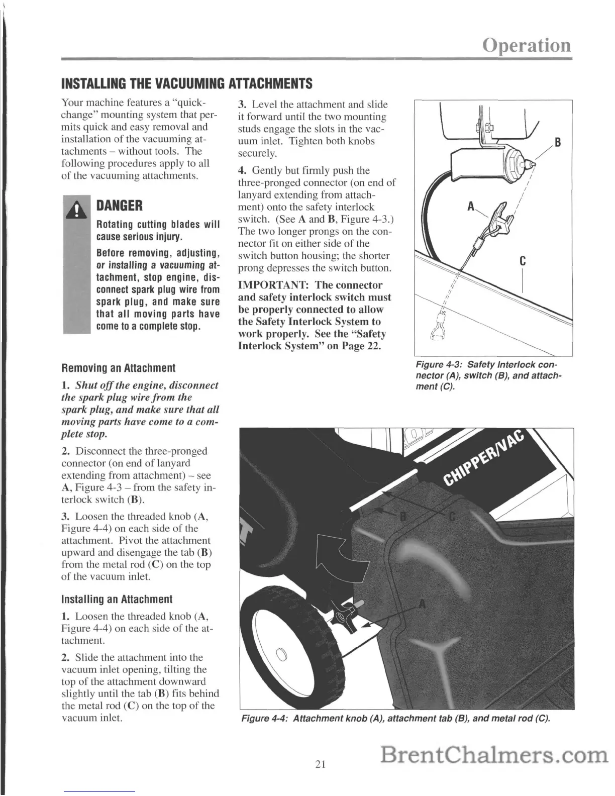
2. Disconnect the three-pronged
connector (on end
of
lanyard
extending from attachment)
- see
A, Figure 4-3 - from the safety in-
terlock switch (B).
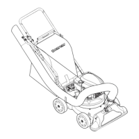
3. Loosen the threaded knob (A,
Figure 4-4) on each side
of
the
attachment. Pivot the attachment
upward and disengage the tab (B)
from the metal rod (C) on the top
of
the vacuum inlet.
Installing
an
Attachment
1. Loosen the threaded knob (A,
Figure 4-4) on each side
of
the at-
tachment.
2. Slide the attachment into the
vacuum inlet opening, tilting the
top
of
the attachment downward
slightly until the tab (B) fits behind
the metal rod
(C) on the top
of
the
vacuum inlet.
3. Level the attachment and slide
it forward until the two mounting
studs engage the slots in the vac-
uum inlet. Tighten both knobs
securely.
4. Gently but firmly push the
three-pronged connector (on end
of
lanyard extending from attach-
ment) onto the safety interlock
switch. (See A and B, Figure 4-3.)
The two longer prongs on the con-
nector fit on either side
of
the
switch button housing; the shorter
prong depresses the switch button.
IMPORTANT: The connector
and safety interlock switch must
be properly connected to allow
the Safety Interlock System to
work properly. See the "Safety
Interlock System" on Page
22.
Figure 4-3:
Safety
Interlock
con-
nector
(A),
switch
(8),
and
attach-
ment(C).
Figure 4-4:
Attachment
knob
(A),
attachment
tab (8),
and
metal
rod
(C).
21