Maintenance/Repairs
REPAIRING
A
DAMAGED
SHREDDER
SCREEN
Periodically inspect the screen for
cracks or bent parts.
• Discard a screen that is cracked.
• A slightly bent crossbar will not
adversely affect operation.
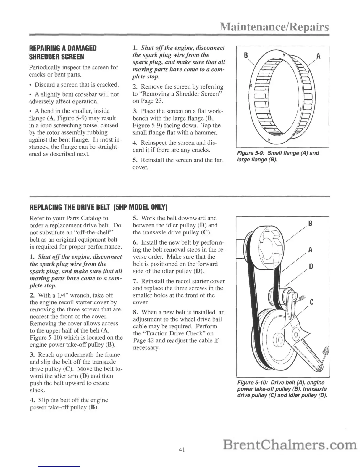
• A bend in the smaller, inside
flange (A, Figure 5-9) may result
in a loud screeching noise, caused
by the rotor assembly rubbing
against the bent flange. In most in-
stances, the flange can be straight-
ened as described next.
1.
Shut
off
the engine, disconnect
the spark plug wire from the
spark plug,
and
make sure that all
movingparts have come
to
a com-
plete stop.
2. Remove the screen by referring
to "Removing a Shredder Screen"
on
Page 23.
3. Place the screen on a flat work-
bench with the large flange (B,
Figure 5-9) facing down. Tap the
small flange flat with a hammer.
4. Reinspect the screen and dis-
card it if there are any cracks.
S.
Reinstall the screen and the fan
cover.
Figure 5-9: Small flange (A)
and
large flange (B).
REPLACING
THE
DRIVE
BELT
(5HP
MODEL
ONLY)
Refer to your Parts Catalog to
order a replacement drive belt. Do
not substitute an "off-the-shelf'
belt as an original equipment belt
is required for proper performance.
1.
Shut
off
the engine, disconnect
the spark
plug
wire
from
the
spark plug,
and
make sure that all
movingparts have come to a com-
plete stop.
2.
With a 1/4" wrench, take
off
the engine recoil starter cover by
removing the three screws that are
nearest the front
of
the cover.
Removing the cover allows access
to the upper half
of
the belt (A,
Figure 5-10) which is located on the
engine power take-off pulley (B).
3. Reach up underneath the frame
and slip the belt
off
the transaxle
drive pulley
(C). Move the belt to-
ward the idler arm (D) and then
push the belt upward to create
slack.
4. Slip the belt off the engine
power take-off pulley (B).
S.
Work the belt downward and
between the idler pulley (D) and
the transaxle drive pulley
(C).
6. Install the new belt by perform-
ing the belt removal steps in the re-
verse order. Make sure that the
belt is positioned on the forward
side
of
the idler pulley (D).
7. Reinstall the recoil starter cover
and replace the three screws in the
smaller holes at the front
of
the
cover.
8. When a new belt is installed, an
adjustment to the wheel drive bail
cable may be required. Perform
the "Traction Drive Check" on
Page 42 and readjust the cable
if
necessary.
41
Figure 5-10: Drive
belt
(A), engine
power
take-offpUlley (B), transaxle
drive
pulley
(e)
and
idler
pulley
(D).