OWNER/OPERATOR
MANUAL
SUPPLEMENT
Installation
and
Use
Instructions
for
New
Style
Engine
Throttle
Control
(Carefully
read
this
Supplement
and
then
insert
it
at
Page
26
of
your
TROY-BILT®
ChipperNac
Manual)
1
You
have received a new style Engine Throttle
• Control that replaces the engine ON/OFF switch
that
is
described in your Manual. Use the infor-
mation on these pages to install and use the new
throttle control and save this Supplement for
future reference.
NEW
LOOSE
HARDWARE
2.
3.
This Supplement contains important Parts
Catalog information. Be sure to update your
Parts Catalog
as
described on Page
3.
If
you have any questions or concerns, contact
your local authorized service dealer, or call or
write our Technical Service Department. See
Page 4 for telephone and address information.
NOTE: The two #10-24 x 1/2" self-threading, Hex/Washer Screws (see
Key "N" on Page 9
of
your Manual) are no longer required.
FOR
MODEL:
4HP
5HP
KEY
QTY.
The loose parts hardware bag con-
tains three new parts that are not
shown or listed on Page 9
of
your
Manual. These parts will be used
to install the new Throttle Control.
Refer to the table to the right and to
Figure I below to identify these
new parts.
NEW
ASSEMBLY
PROCEDURE
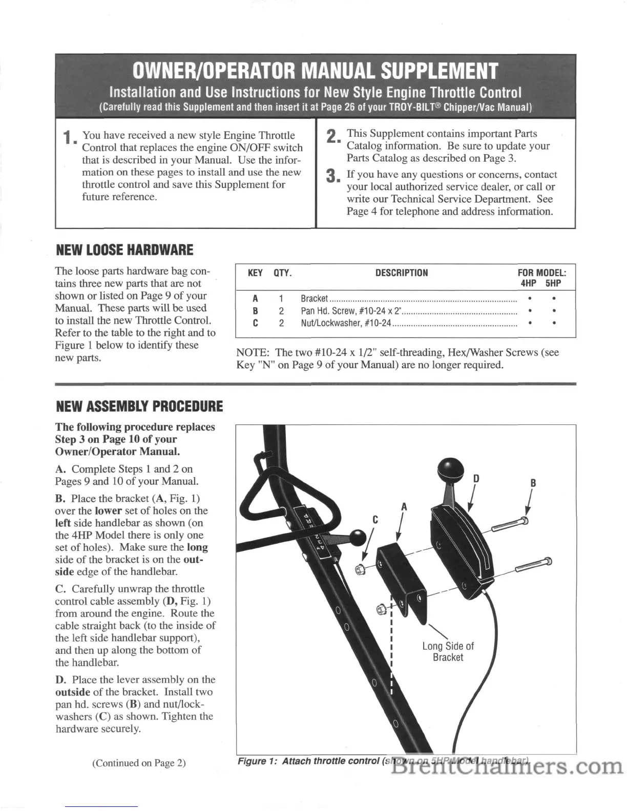
A
B
C
DESCRIPTION
1
Bracket
•
2
Pan
Hd.
Screw,
#10-24
x 2".................................................. •
2
NutiLockwasher,
#10-24...................................................... •
•
•
•
The
following procedure replaces
Step 3
on
Page
10
of
your
Owner/Operator
Manual.
A. Complete Steps 1 and 2 on
Pages 9 and 10
of
your Manual.
B. Place the bracket (A, Fig.
1)
over the lower set
of
holes on the
left side handlebar as shown (on
the 4HP Model there is only one
set
of
holes). Make sure the long
side
of
the bracket is on the out-
side edge
of
the handlebar.
C. Carefully unwrap the throttle
control cable assembly (D, Fig.
1)
from around the engine. Route the
cable straight back (to the inside
of
the left side handlebar support),
and then up along the bottom
of
the handlebar.
D. Place the lever assembly on the
outside
of
the bracket. Install two
pan hd. screws (B) and nut/lock-
washers (C)
as
shown. Tighten the
hardware securely.
(Continued on Page 2)
Figure 1:
Attach
throttle
control
(shown
on
5HP Model handlebar).