Maintenance/Repairs
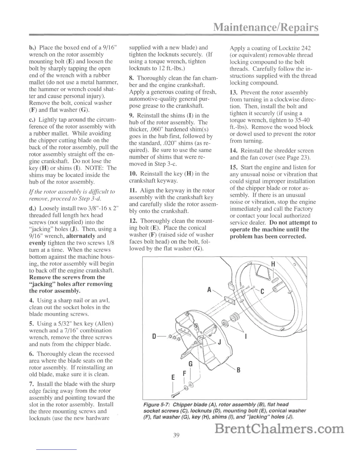
Figure
5-7:
Chipper
blade
(A),
rotor
assembly
(8),
flat
head
socket
screws
(C),
locknuts
(D),
mounting
bolt
(E),
conical
washer
(F),
flat
washer
(G),
key
(H),
shims
(I),
and
'jacking"
holes
(J).
b.) Place the boxed end
of
a 9/16"
wrench on the rotor assembly
mounting bolt (E) and loosen the
bolt by sharply tapping the open
end
of
the wrench with a rubber
mallet (do not use a metal hammer,
the hammer or wrench could shat-
ter and cause personal injury).
Remove the bolt, conical washer
(F) and flat washer (G).
c.) Lightly tap around the circum-
ference
of
the rotor assembly with
a rubber mallet. While avoiding
the chipper cutting blade on the
back
of
the rotor assembly, pull the
rotor assembly straight off the en-
gine crankshaft. Do not lose the
key
(H) or shims (I). NOTE: The
shims may be located inside the
hub of the rotor assembly.
If
the rotor assembly is difficult
to
remove, proceed to Step 3-d.
d.) Loosely install two 3/8"-16 x
2"
threaded full length hex head
screws (not supplied) into the
"jacking" holes
(J). Then, using a
9/16" wrench,
alternately
and
evenly tighten the two screws
1/8
turn at a time. When the screws
bottom against the machine hous-
ing, the rotor assembly will begin
to back off the engine crankshaft.
Remove
the
screws
from
the
"jacking"
holes
after
removing
the
rotor
assembly.
4. Using a sharp nail or an awl,
clean out the socket holes in the
blade mounting screws.
5. Using a 5/32" hex key (Allen)
wrench and a 7/16" combination
wrench, remove the three screws
and nuts from the chipper blade.
6.
Thoroughly clean the recessed
area where the blade seats on the
rotor assembly.
If
reinstalling an
old blade, make sure it
is
clean.
7. Install the blade with the sharp
edge facing away from the rotor
assembly and pointing toward the
slot
in
the rotor assembly. Install
the three mounting screws and
locknuts (use the new hardware
supplied with a new blade) and
tighten the locknuts securely. (If
using a torque wrench, tighten
locknuts to
12
ft.-lbs.)
8. Thoroughly clean the fan cham-
ber and the engine crankshaft.
Apply a generous coating
of
fresh,
automotive-quality general pur-
pose grease to the crankshaft.
9. Reinstall the shims (I) in the
hub
of
the rotor assembly. The
thicker, .060" hardened shim(s)
goes
in
the hub first, followed by
the standard, .020" shims (as re-
quired). Be sure to use the same
number of shims that were re-
moved in Step 3-c.
10.
Reinstall the key (H) in the
crankshaft keyway.
11. Align the keyway
in
the rotor
assembly with the crankshaft key
and carefully slide the rotor assem-
bly onto the crankshaft.
12. Thoroughly clean the mount-
ing bolt
(E). Place the conical
washer
(F)
(raised side
of
washer
faces bolt head) on the bolt, fol-
lowed by the flat washer
(G).
G
E
~
1)
I~
f7?
Apply a coating
of
Locktite 242
(or equivalent) removable thread
locking compound to the bolt
threads. Carefully follow the
in-
structions supplied with the thread
locking compound.
13. Prevent the rotor assembly
from turning in a clockwise direc-
tion. Then, install the bolt and
tighten
it
securely (if using a
torque wrench, tighten to 35-40
ft.-lbs). Remove the wood block
or dowel used to prevent the rotor
from turning.
14. Reinstall the shredder screen
and the fan cover (see Page 23).
15. Start the engine and listen for
any unusual noise or vibration that
could signal improper installation
of
the chipper blade or rotor as-
sembly.
If
there
is
an unusual
noise or vibration, stop the engine
immediately and call the Factory
or contact your local authorized
service dealer. Do
not
attempt
to
operate
the
machine
until the
problem
has been corrected.
39