18
SECTION 8: SERVICE
Cutting Blades
• Periodically inspect the blade adapter and/or
spindle for cracks or damage, especially if you
strike a foreign object. Replace immediately if
damaged
.
To remove blade:
• Remove the deck from beneath the tractor, (refer to
Cutting Deck Removal on page 18). Then gently flip
the deck over to expose its underside.
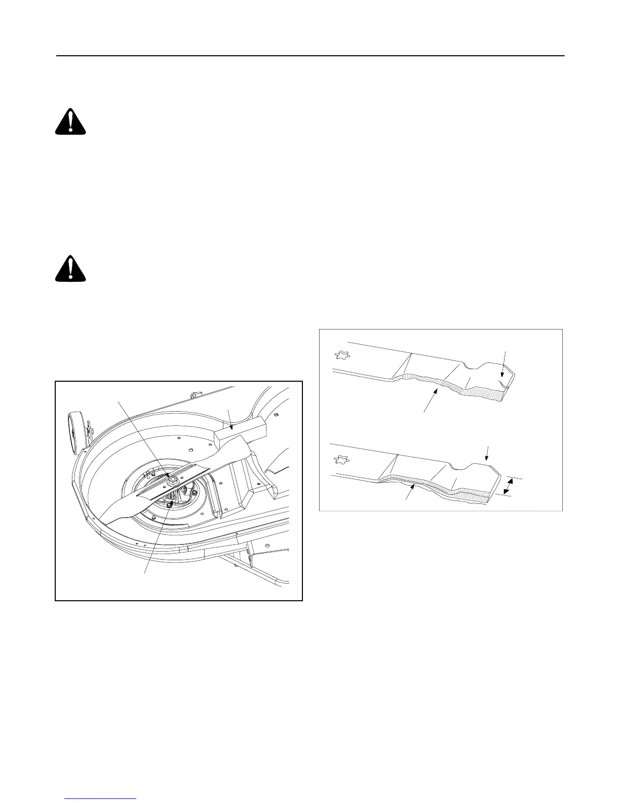
• Place a block of wood between the center deck
housing baffle and the cutting blade to act as a
stabilizer. See Figure 9 .
Figure 9
• Use a 15/16" wrench to remove the hex flange nut
that secures blade to the spindle assembly. See
Figure 9 .
To sharpen blades:
• Remove equal amounts of metal from both ends of
the blades along the cutting edges, parallel to the
trailing edge, at a 25° to 30° angle. See Figure 10 .
• If the cutting edge of the blade has already been
sharpened to within 5/8" of the wind wing radius, or
if any metal separation is present, replace the
blades with new ones. See Figure 10 .
• Grind each blade edge equally to maintain proper
blade balance.
• Test the blade by balancing it on a round shaft
screwdriver. Grind metal from the heavy side until it
balances evenly.
IMPORTANT:
A poorly balanced blade will cause
excessive vibration and may cause damage to the
tractor and/or personal injury.
To replace blade:
• When replacing the blade, be sure to install the
blade with the side marked ‘‘Bottom’’ (or with a part
number stamped in it) facing the ground when the
mower is in the operating position.
• Use a torque wrench to tighten the blade spindle
hex flange nut to between 70 foot-pounds and 90
foot-pounds.
Figure 10
Removing Cutting Deck
• Place the PTO lever in the disengaged (OFF)
position and engage the parking brake.
• Lower the deck by moving the deck lift lever into the
bottom notch on the right fender.
• Remove the PTO belt from around the cutting
deck’s center pulley. Refer to .
• Looking at the cutting deck from the left side of the
tractor, locate the deck support pin on the rear left
side of the deck.
• Pull the deck support pin outward to release the
deck from the deck lift arm. See Figure 11.
• Rotate the pin slightly toward the rear of the tractor
and release the pin into the hole provided. Repeat
on the right side.
WARNING: Before performing any
maintenance or repairs, disengage PTO, move
shift lever into neutral position, set parking
brake, stop engine and remove key to prevent
unintended starting.
WARNING: Protect your hands by using
heavy gloves or a rag to grasp the blade.
Spindle Assembly
Hex Flange Nut
Wood Block
Blade Separation
Worn Blade Edge
Wind Wing
Sharpen edge evenly
5
/
8
"
m
i
n
i
m
u
m