TIPS FOR BEST TRIMMING RESULTS
• For best trimming results, operate unit at full throttle.
• Keep the cutting attachment parallel to the ground.
• Do not force the cutting attachment. Allow the tip of the line to do the cutting,
especially along walls. Cutting with more than the tip will reduce cutting
efficiency and may overload the engine.
• Cut grass over 8 inches (200 mm) by working from top to bottom in small increments
to avoid premature line wear or engine drag.
• Slowly move the trimmer into and out of the cutting area at the desired height. Move
either in a forward-backward or side-to-side motion.
Cutting shorter lengths produces the best results.
• Trim only when grass and weeds are dry.
• The life of your cutting line is dependent upon:
• Proper adherence of explained trimming techniques
• What vegetation is cut
• Where vegetation is cut
For example, the line will wear faster when trimming against
a foundation wall as opposed to trimming around a tree.
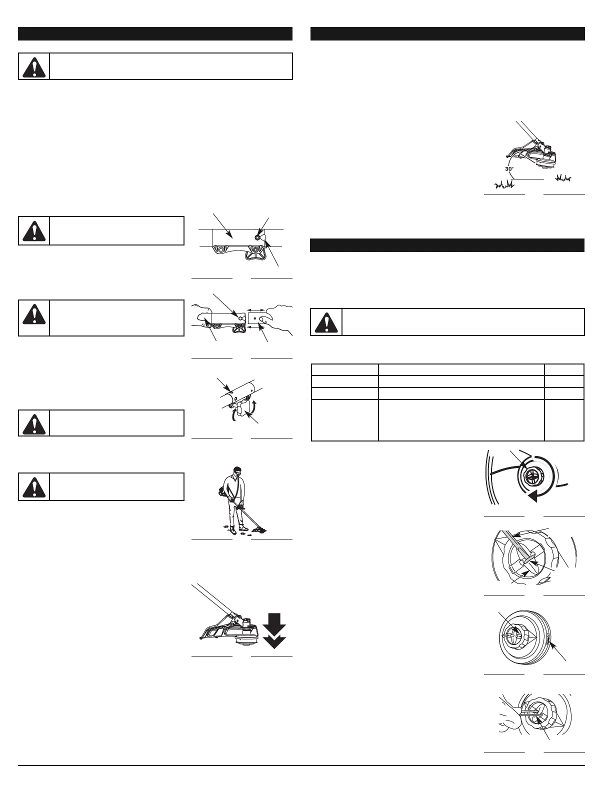
DECORATIVE TRIMMING
Decorative trimming is accomplished by removing all vegetation around trees, posts,
fences and more.
Rotate the whole unit so that the cutting attachment is at a 30° angle to the ground (Fig. 18).
OPERATING INSTRUCTIONS
MAINTENANCE AND REPAIR INSTRUCTIONS
MAINTENANCE SCHEDULE
Perform these required maintenance procedures at the frequency stated in the table.
These procedures should also be a part of any seasonal tune-up.
NOTE: Some maintenance procedures may require special tools or skills. If you are
unsure about these procedures take your unit to any non-road engine repair
establishment, individual or authorized service dealer.
NOTE: Maintenance, replacement, or repair of the emission control devices and
system may be performed by any non-road engine repair establishment,
individual or authorized service dealer.
WARNING:
To prevent serious injury, never perform maintenance or
repairs with unit running. Always service and repair a cool unit. Disconnect
the spark plug wire to ensure that the unit cannot start.
REMOVING THE LINE
1. Rotate the bump knob clockwise until all line is
inside the cutting head (Fig. 19).
2. Using a flat-head screwdriver, insert the tip into the
line dimple and just under the exposed portion of
the line (Fig. 20)
3. Pull the line straight out until all line is removed from
the cutting head.
LINE INSTALLATION
Always use original equipment manufacturer 0.095 in.
(2.41 mm) replacement line.
1. Align the arrows on the bump knob with the spool
cover eyelets, if they are not already (Fig. 21).
2. Using 16 ft. (3.2 m) of 0.095 in. (2.41 mm) replacement
line push both ends of the line through the holes in the
bump knob until they protrude through the eyelets on
both sides of the cutting head. Continue pulling the line
until approximately 6 ft. (1.5 m) is visible from both
sides of the cutting head. (Fig. 22)
3. Hold the spool cover, turn the bump knob clockwise
to wind the line around the spool until about 5 in.
(12.7 cm) is protruding from each side of the cutting
head. (Fig. 19)
4. Start the unit and bump the cutting head on the
ground until the desired cutting length is achieved.
Excess line will be trimmed off by the line blade.
NOTE: If the cutting line ends are pulled into the
cutting head or the line becomes twisted,
refer to Removing the Line.
5
Flat-Head
Screw Driver
Arrows
Trimmer
Line
Dimple
Eyelet
Trimmer line
OPERATING THE EZ-LINK™ SYSTEM
The EZ-Link™ system enables the use of these optional Add-Ons:
Mach 4® Trimmer . . . . . . . . . . . . . . . . . . . . . . . . . . . . . . . . . . . . . . . . . . . . . . . . . . . AF720
Hedge Trimmer . . . . . . . . . . . . . . . . . . . . . . . . . . . . . . . . . . . . . . . . . . . . . . . . . . . . AH720
Brushcutter . . . . . . . . . . . . . . . . . . . . . . . . . . . . . . . . . . . . . . . . . . . . . . . . . . . . . . . BC720*
Blower/ Trimmer . . . . . . . . . . . . . . . . . . . . . . . . . . . . . . . . . . . . . . . . . . . . . . . . . . . . BT720
Blower Vacuum. . . . . . . . . . . . . . . . . . . . . . . . . . . . . . . . . . . . . . . . . . . . . . . . . . . . . BV720
Cultivator. . . . . . . . . . . . . . . . . . . . . . . . . . . . . . . . . . . . . . . . . . . . . . . . . . . . . . . . . GC720
Edger. . . . . . . . . . . . . . . . . . . . . . . . . . . . . . . . . . . . . . . . . . . . . . . . . . . . . . . . . . . . . LE720
Pole Saw . . . . . . . . . . . . . . . . . . . . . . . . . . . . . . . . . . . . . . . . . . . . . . . . . . . . . . . . . PS720
Straight Shaft Trimmer. . . . . . . . . . . . . . . . . . . . . . . . . . . . . . . . . . . . . . . . . . . . . . . SS725
Snow Thrower. . . . . . . . . . . . . . . . . . . . . . . . . . . . . . . . . . . . . . . . . . . . . . . . . . . . . . ST720
Turbo Blower . . . . . . . . . . . . . . . . . . . . . . . . . . . . . . . . . . . . . . . . . . . . . . . . . . . . . . TB720
*Do NOT use this attachment with an electric powered unit.
Removing the Cutting Attachment or Add-On
1. Turn the knob counterclockwise to loosen (Fig. 15).
2. Press and hold the release button (Fig. 13).
3. While firmly holding the upper shaft housing, pull the
cutting attachment or add-on straight out of the EZ-
Link™ coupler (Fig. 14).
Installing the Cutting Attachment or Add-On
NOTE:
Place the unit on the ground or on a work bench
to make add-on installation or removal easier.
1. Turn knob counterclockwise to loosen (Fig. 15).
2. While firmly holding the add-on, push it straight into
the EZ-Link™ coupler (Fig. 14).
NOTE: Aligning the release button with the guide
recess will help installation (Fig. 13).
3. Turn the knob clockwise to tighten (Fig. 15).
For edging (when using the line head cutting attachment
with EZ-Link™ models), lock the release button of the cutting attachment into the 90° edging
hole (Fig. 15).
HOLDING THE TRIMMER
Before operating the unit, stand in the operating
position (Fig. 16). Check for the following:
• The operator is wearing eye protection and proper
clothing
• With a slightly-bent right arm, the operator’s right
hand is holding the shaft grip
• The operator’s left arm is straight, the left hand holding the handle
• The unit is at waist level
• The cutting attachment is parallel to the ground and easily contacts the grass without
the need to bend over
ADJUSTING TRIMMING LINE LENGTH
The cutting head allows you to release trimming line
without stopping the engine. To release more line, lightly
tap the cutting attachment on the ground (Fig. 17) while
operating the trimmer at high speed.
NOTE: Always keep the trimming line fully extended.
Line release becomes more difficult as the
cutting line becomes shorter.
Each time the head is bumped, about 1 inch (25.4 mm)
of trimming line is released. A blade in the cutting attachment shield will cut the line to the
proper length if excess line is released.
For best results, tap the cutting head on bare ground or hard soil. If line release is
attempted in tall grass, the engine may stall. Always keep the trimming line fully
extended. Line release becomes more difficult as the cutting line becomes shorter.
NOTE: Do not rest the cutting head on the ground while the unit is running.
Some line breakage will occur from:
• Entanglement with foreign matter
• Normal line fatigue
• Attempting to cut thick, stalky weeds
• Forcing the line into objects such as walls or fence posts
WARNING:
Before you begin using any attachment, read and
understand the manual that came with the attachment. Follow all safety
information contained within.
WARNING:
To avoid serious personal
injury and damage to the unit, shut the unit
off before removing or installing add-ons.
CAUTION:
Lock the release button in
the primary hole and securely tighten the
knob before operating this unit.
CAUTION:
Add-ons are to be used in
the primary hole only. Using the wrong
hole could lead to personal injury or
damage to the unit.
Guide Recess
Fig. 13
Release
Button
EZ-Link
™
Coupler
Upper Shaft
Housing
Fig. 14
Lower Shaft
Housing
Primary Hole
Knob
Fig. 15
90˚ Edging Hole
(Trimmer Only)
OPERATING INSTRUCTIONS
Bump
Knob
WARNING:
Always wear eye, hearing,
foot and body protection to reduce the
risk of injury when operating this unit.
Fig. 16
FREQUENCY MAINTENANCE REQUIRED SEE
Every 10 hours Clean and oil air filter p. 6
Change 1st 10 hours Change oil p. 6
Every 40 hours
Change oil
Clean spark arrestor and change oil
Check rocker arm to valve clearance and adjust
Check spark plug condition and gap
p. 6
p. 6
p. 6
p. 6
Fig. 17
Fig. 22
Fig. 21
Fig. 20
Fig. 19
Fig. 18