10
TRUE
milk coolers
www.truemfg.com
WHEN TO MAKE AN ADJUSTMENT TO A MECHANICAL TEMPERATURE CONTROL
W
A
R
M
E
R
C
O
L
D
E
R
30
40
35
50
55
20
25
10
5
We advise to make a mechanical temperature control adjustment only for a high altitude location.
Compressor
Ter minals
Ground
Ter minal
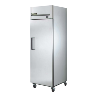
To adjust the temperature control
take the control knob off to view the
cut-in screw. (See Photo Above)
Front of Temperature Control
Calibration
Screw
1 2
3
ALTITUDE CORRECTION TABLE:
CALIBRATION SCREW ADJUSTS
BOTH CUT-IN AND CUT-OUT
Altitude (Feet)
2000
3000
4000
5000
6000
7000
8000
9000
10,000
Clockwise Turns
7/60
11/60
15/60
19/60
23/60
27/60
30/60
34/60
37/60
HOW TO ADJUST A MECHANICAL TEMPERATURE CONTROL
Altitude Correction
Scale Guide for Measuring
Back of Temperature
Control
GE TEMPERATURE CONTROL ADJUSTMENT FOR
HIGH ALTITUDE APPLICATIONS:
REQUIRED TOOLS:
• Jewelers screwdriver (Small screwdriver)
GE CONTROL INSTRUCTIONS:
The scale to the right may be used as a guide for measuring
degrees of rotation required for altitude correction. See
Figure 1. The arrows indicate direction of screw rotation.
Turn calibration screw clockwise to obtain warmer operating
temperatures.
STEP 1 - Unplug cooler.
STEP 2 - Remove the screws that secure the temperature
control to the inset box.
STEP 3 - To make these adjustments it may be necessary to
remove the temperature control from the housing.
NOTE: You may have to remove the wires attached to the
control. Take note as to which wire is on which spade terminal.
STEP 4 - Pull out gently from cabinet.
STEP 5 Each 1/4 turn of the calibration screw is equal to
approximately 2 degrees F. Do not make more than 3/4 turn.
After making adjustment, measure temperature during three
cycles before adjusting again.
NOTE: Only adjust the screw (small flathead) on the face of
the control (next to the cam). See Figure 3.
STEP 6 - Make sure to reconnect the wires to the proper
spade terminal when reinstalling.
Follow the Altitude Correction Table to the right.
MECHANICAL TEMPERATURE CONTROLS