4
Control panel installation
When using vehicle-specific or manufacturer-specific
control panels, the electrical connection must be made
according to the Truma interface description.
Any modifications to the associated Truma parts will invali-
date the warranty and preclude any liability claims. The instal-
ler (manufacturer) is responsible for providing the user with
operating instructions and the information that is printed on
the control panels.
When choosing a location, please note that the control panel (20)
must not be subjected to direct heat radiation. Length of con-
nector cable 2.5 m.
If the control panel cannot be flush-mounted, Truma can
provide an on-surface frame (18 – part no. 40000-52600)
as an accessory if required.
Drill hole with diameter of 55 mm. Guide through the cable(19)
towards the rear and secure the control panel (20) with
4screws(21). Then clip on the cover frame (22) and route
cable (19) to boiler.
19
22
18
20
21
Figure 4
Truma supplies side parts (23) as accessories to improve
the appearance of the cover frame (22). Please contact your
dealer.
230 V electrical connection
The electrical connection must always be made by
an expert (in accordance with VDE 0100, part 721 or
IEC60364-7-721 in Germany).
The power connection is made using a 3 x 1.5 mm² cable (e.g.
hose line H05VV-F) to a distribution socket (figs. A + B: 24 –
not included in scope of delivery). A connector cable with a
plug is not permitted.
It is imperative that connection is carried out with care while
observing the correct colours!
An insulating device for providing all-pole insulation from
the mains with contact clearance of at least 3.5 mm
must be provided by the customer for carrying out mainten-
ance and repair work.
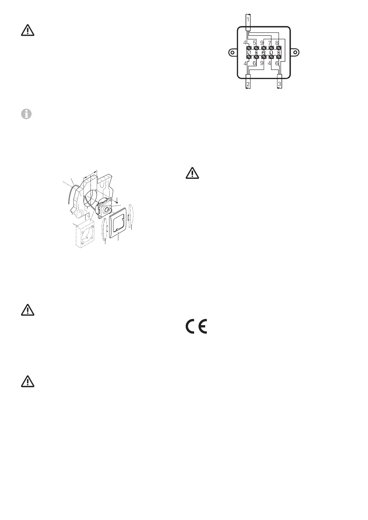
Figs. A + B
Attach the distribution socket (24) to floor or wall of vehicle
near device (cable length 110 cm).
Connect control panel cable, 230 V supply cable and heating
element cable in accordance with connection plan.
Figure 5
1 = Control panel cable
2 = Supply cable 3 x 1.5 mm²
3 = Heating element cable
4 = brown
5 = green
6 = blue
7 = yellow
8 = white
9 = yellow/green
All cables must be secured with clamps.
Function check
The water connections must be checked for leaks and all
functions must be tested as described in the operating in-
structions after installation.
Then it must be ensured that all of the water (14 litres) drains
when the system is emptied.
No claims may be made under the warranty for damage
caused by frost.
Warnings
The yellow sticker containing warning information that is en-
closed with the appliance must be affixed by the installer or
vehicle owner in a location in the vehicle where it is clearly
visible to all users (e.g. on the wardrobe door)! Missing stick-
ers can be requested from Truma.
Subject to technical changes.