12
Electrical connection 230 V ~ / 240 V ~
– option –
All electrical work and permanent wiring must be car-
ried out by a qualified person and in accordance with
the standards AS/NZS 3000, AS/NZS 3001 and all local codes
and regulatory authority requirements.
The electric heating element in the water heater is supplied
with a mains cable and fitted 3-pole, earthed plug (in compli-
ance with the standard AS/NZS 3112/2000).
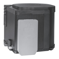
Fig. 21
In order to operate the element the manufacturer of the
vehicle has to supply and install a socket with switch (2-pole
separation) which is approved in Australia and earthed.
All cables must be secured with cable clips.
Cables must be in accordance with the technical rules and
regulations of the country in which the vehicle is to be
registered for the first time.
Function check
After installation, check gas supply line for leaks in accord-
ance with the pressure drop method. Following this, check
the function of the appliance as specified in the operating in-
structions, in particular, check that the water drains properly.
Warranty claims for frost damage will not be accepted.
Never operate the water heater without water. It is, how-
ever, possible to briefly check the electrical function without
water. Always observe the operating instructions prior to
operation!
The operating instructions and completed warranty card are
to be given to the owner of the vehicle.
Accessories
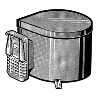
Drain valve and water connectors for flexible water
hoses
34020-63900 Hot water connector, 10 mm
34020-16900 Cold water connector, 10 mm
70141-02 Drain valve (280 kPa), 10 mm
Fig. 22
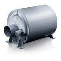
Cowl extension for wall thicknesses over 35 mm
70131-00 Cowl extension VBO 2
Fig. 23
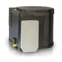
Control panel extension cable
70000-53500 Control extension cable 5 m
Fig. 24
Surface-mounting frame (not illustrated)
40000-52600
 Loading...