18
Truma pressure relief/drain valve
Risk of scalding injury from hot water
and/or tampering with the pressure relief/
drain valve!
• Never actuate the lever as long as the
Combi furnace is under water pressure
and/or still hot.
• Do not place a plug or reducing coupling
on the outlet part of the valve. If you use a
discharge line, allow the valve and the line
to drain completely.
– The Truma pressure relief/drain valve pro-
vides both the pressure relief function and
a drain function.
– The pressure relief/drain valve is a safety
component and must not be removed for
any reason other than replacement.
– The pressure relief/drain valve is not ser-
viceable; if defective, it must be replaced.
It must be replaced by a certified service
technician.
– It must only be replaced by the Truma
pressure relief/drain valve rated for
65.25psi (4.5 bar) which is CSA certified
and registered.
– Tampering with the pressure relief/drain
valve will void the warranty.
• Operate the valve manually at least once per
year to ensure that water channels are clear.
• Before lifting the lever (Fig.7–2), make sure
that the discharge line is securely attached
and properly installed, to prevent injury and
property damage.
• If no water flows when the lever is operated,
check the water supply.
– The water pump must be turned on or the
RV must be connected to city water.
• The pressure relief/drain valve should be in-
spected every three years by a qualified ser-
vice technician and be replaced if necessary.
2
3
1
a
b
c
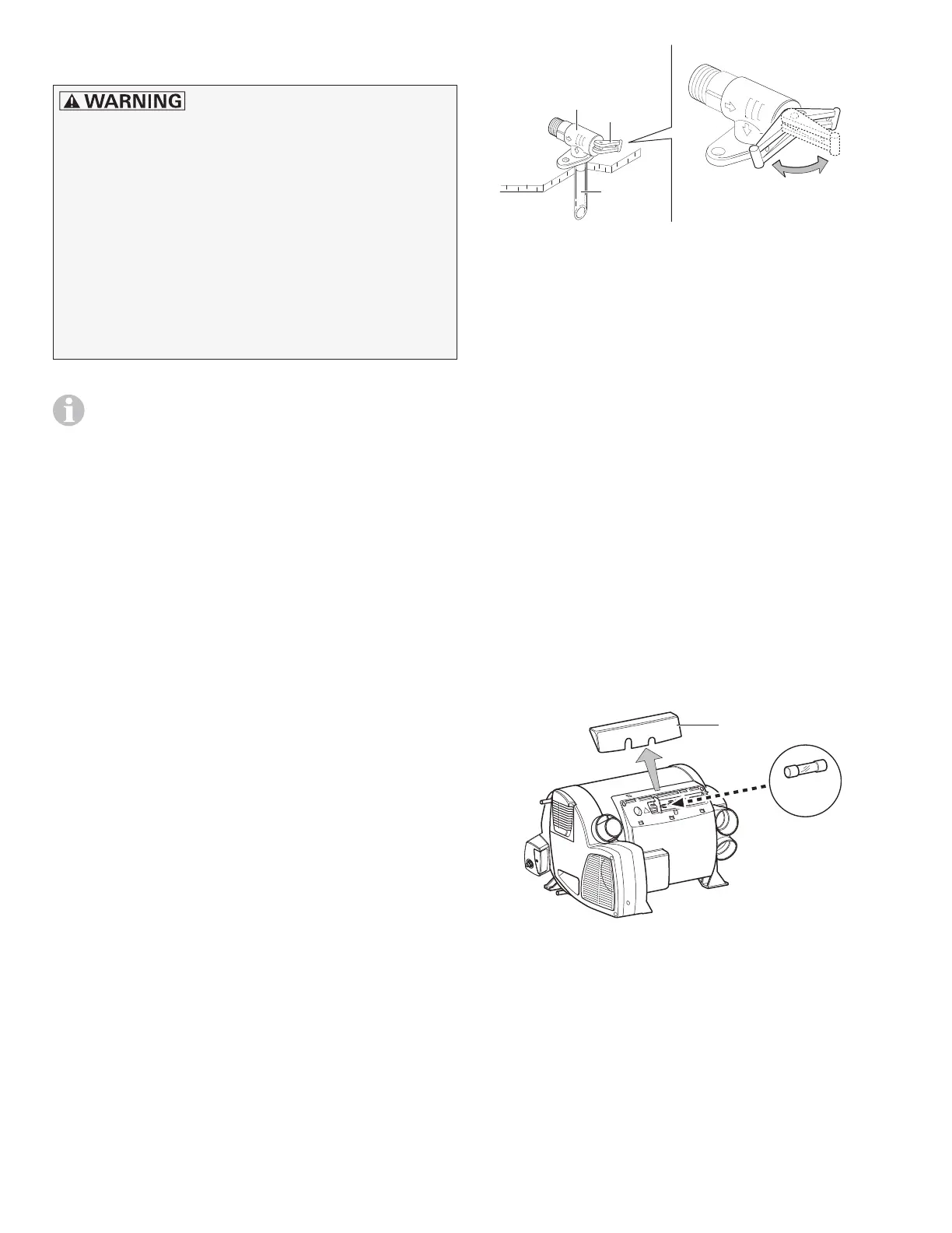
Fig. 7
a,b = lever in “valve closed during furnace op-
eration” position
c = lever in “draining” position
Replacing the 12-volt fuse
Only a qualified service technician may perform
this task.
The fuse is on the printed circuit board under-
neath the connection cover.
• While detaching or reattaching the connec-
tion cover (Fig. 8 – 5), take care to neither
dislodge nor pinch the connector cables.
• A defective fuse must be replaced with the
same make and model of fuse.
10AT time-lag, 5X20 mm. IEC60127-2 Standard
T 10 A
5
Fig. 8