6
The diagram shows right-handed installation. With
left-handed installation, some parts are located on the
other side (mirror inverted)
Start-up
Burner ignition
Before operation, ensure that there is a new battery with suffi-
cient charge in the auto ignitor.
Possible risk of misfiring! Reduced ignition frequency
due to an old or weak battery in the auto ignitor.
– At least two ignition sparks must be visible per second.
– If this is not the case, replace the battery in the auto ignitor
(see “Auto ignitor battery change”).
1. Open the gas cylinder and quick-acting valve in the gas
supply line.
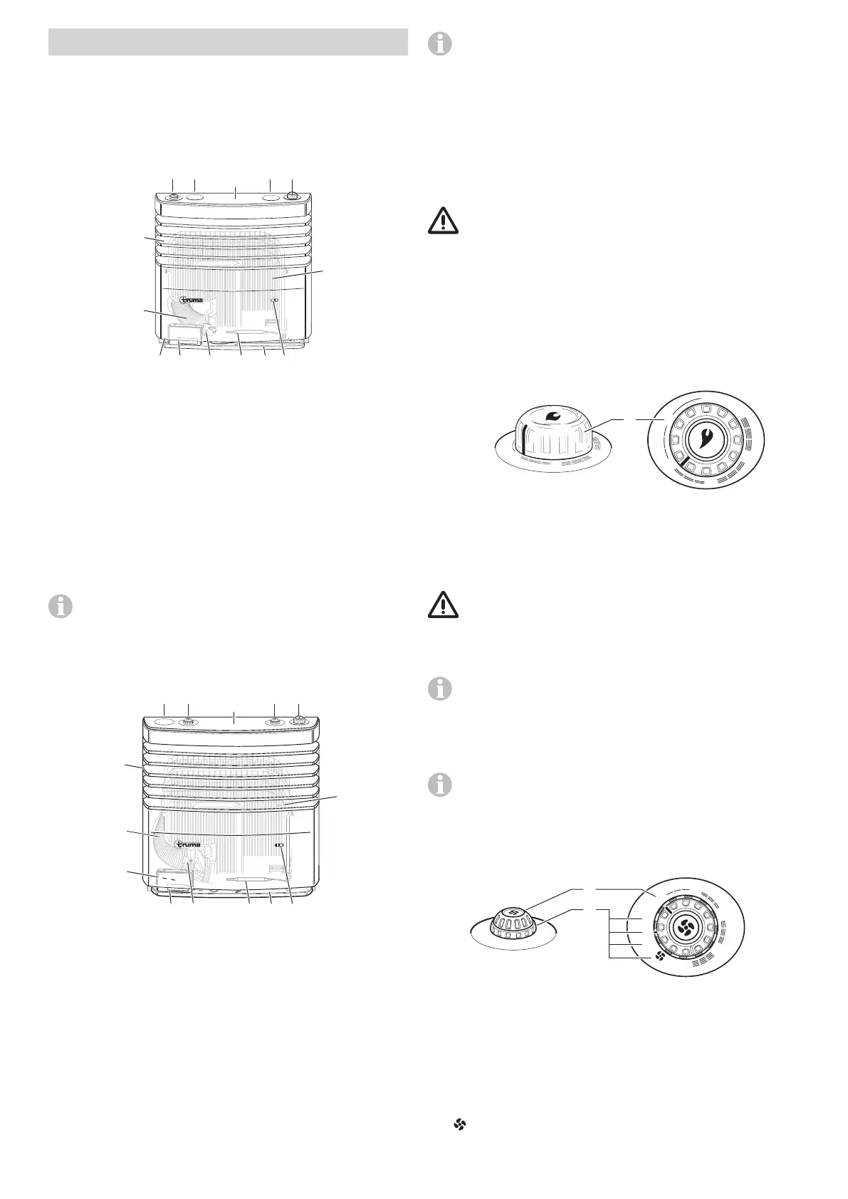
2. Turn the control knob (Figure 3 – 1) to the thermostat po-
sition 1 – 5 and push in as far as it will go (maximum 30sec-
onds). Ignition with an audible ignition spark takes place auto-
matically in this period.
0
1
2
3
4
5
5
4
2
1
1
Figure 3
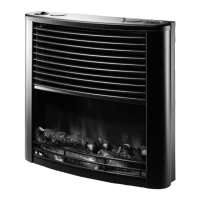
3. Monitor the ignition process through the mica window
(Figure 1 – 6 or 2 – 6). A flame can be seen when ignition is
successful.
4. After a successful ignition, keep the control knob held down
for another 10 seconds so that the safety pilot responds.
Possible risk of misfiring!
– Wait for at least three minutes before trying again if there is
a fault or if ignition was unsuccessful.
– Contact service following three unsuccessful ignition attempts.
If the flame goes out during operation, immediate
automatic re-ignition takes place within the closing time of
the safety pilot (approx. 30 seconds). In the event that ignition is
unsuccessful despite repeated attempts (e.g. because the gas
cylinder is empty), the auto ignitor continues to operate until
the control knob (Figure 3 – 1) is set to “0”.
In order to achieve even and quick warm air distribution
and to lower the surface temperatures at the warm air
outlet grille, we recommend operating the heater with the
Truma warm air system running.
Operation of the fan
5
4
3
2
1
A
O
M
b
a
Figure 4
a = Control knob / dial for fan power (1 – 5)
b = Rotary switch / dial for operating modes
A Automatic – The electronics control the required
fan power and limit the speed to
the value set at the control knob.
0 OFF – Switch off fan.
M Manual – Adjusting the fan power.
Booster level
– Set fan speed to the highest value
(for maximum air volume flow).
Design
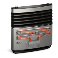
Truma S 3004
4
5
12
13
Figure 1
1 = Control knob (thermostat)
2 = Blind cover
3 = Integrated control panel for a fan TEB-3
4 = Sensor surface for switching the lighting on (optional)
5 = Heat exchanger
6 = Mica window for observing the flame
7 = Base plate
8 = Thermostat sensor
9 = Exhaust gas connection (exhaust connection, pressure
plate, O-ring)
10 = Auto ignitor with battery compartment
11 = Type plate
12 = Exhaust duct
13 = Warm air outlet / cover
The diagram shows right-handed installation. With
left-handed installation, some parts are located on the
other side (mirror inverted).
Truma S 5004
5
11 10
7
12
9 8
13
14
Figure 2
1 = Control knob (thermostat)
2 = Integrated control panel for a TEB-3 Truma fan
3 = Integrated control panel for a second TEB-3 Truma fan
4 = Blind cover
5 = Sensor surface for switching the lighting on (optional)
6 = Mica window for observing the flame
7 = Heat exchanger
8 = Base plate
9 = Thermostat sensor
10 = Exhaust gas connection (exhaust connection, pressure
plate, O-ring)
11 = Auto ignitor with battery compartment
12 = Type plate
13 = Exhaust duct
14 = Warm air outlet / cover
Operating instructions

 Loading...