5. MAINTENANCE page 19
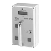
Model PRM-470B
5. MAINTENANCE
5.1. MAINTENANCE PROCEDURES
The PRM-470B has been designed for continuous use up to 50 hours on a set of batteries. Once
initial installation has been completed, little maintenance is required. Periodic inspection is
recommended to insure proper functioning. It is recommended that a copy of the Calibration
Checklist (section 5.3.) be filled out whenever the PRM-470B is put into service after repair or
recalibration.
5.2. ELECTRONIC CALIBRATION PROCEDURE
The following is a list of the equipment required for the electronic calibration procedure. These
steps should only be performed by qualified service personnel.
• Oscilloscope
• Tweaker or small slotted screwdriver
• Digital voltmeter
• 5-10µCi
137
Cs test source
5.2.1. Gain (HV) Adjustment:
Refer to "HHV-454 High Voltage Power Supply Schematic Diagram" Drawing 6 and "HHV-454
High Voltage Power Supply Component Designator" Drawing 7 (Appendix F.).
Place
137
Cs source on the detector. Adjust the high voltage pot which is found in the copper
shielded H.V. board until a 3.2 volt pulse amplitude is obtained. Refer to "Typical Pulse Profile"
Drawing 10 (Appendix F.).