3-1
CHAPTER 3
Communications
There are two modes of communication from the Instrument. The
diagnostic port is RS-232 and can communicate with specific TSI
software. The pulse output is RS-422.
Pulse Output
The pulse output is RS422 using 5 volt differential pulse. The
following describes the pin outs and wiring diagrams.
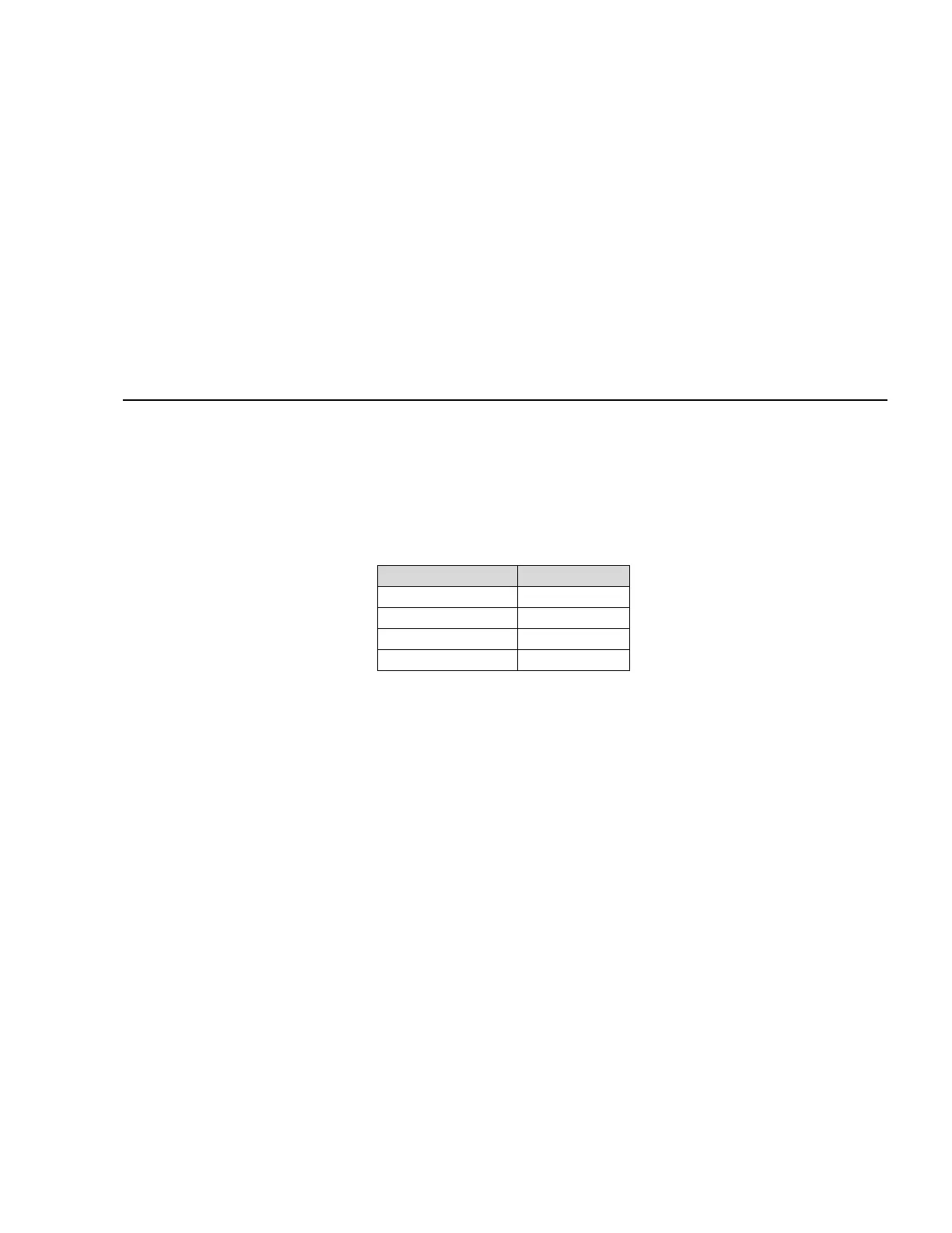
Four-Channel CEMS Mapping
CEMS Channel Size Microns
Ch 1 0.1
Ch 2 0.2
Ch 3 0.3
Ch 4 0.5
DB-15 CEMS pinout
1) Chassis Ground
2) CH1-
3) CH1+
4) CH2-
5) CH2+
6) ST1-
7) ST1+
8) Reserved
9) GND
10) CH3+
11) CH3-
12) CH4+
13) CH4-
14) Reserved
15) GND