Technical Section
Diagnostics menu
The items in the diagnostic menu (listed below) aid in identifying problems the staff may
encounter. The items in this menu temporarily change the function by pressing the /
keys. No permanent change occurs with these menu items. Items are exited by pressing
the MENU key. When an item is exited, the PresSura controller returns to its normal
state.
Sensor Input
Menu item - SENSOR INPUT / 2SENSOR IN
The SENSOR INPUT (2SENSOR IN) item is used to verify that the DIM or
monitor electronics is receiving a signal from the sensor. When this item is
entered, a voltage will be indicated on the display. The exact voltage displayed is
relatively unimportant. It is more important that the voltage is changing which
indicates the sensor is working correctly.
0 volts represents a negative pressure of -0.2 inches H
2
O.
5 volts represents 0 pressure.
10 volts represents a positive pressure of +0.2 inches H
2
O.
Sensor Communications
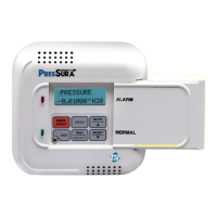
Menu Item - SENSOR STAT / 2SENSOR STAT
The SENSOR STAT (2SENSOR STAT) item verifies that the RS-485
communications between the pressure sensor and DIM is working correctly.
Sensor error messages do not display on DIM except when SENSOR STAT item
is selected. The item will display NORMAL if communications are established
correctly. If problems exist, one of four error messages will display:
COMM ERROR - DIM cannot communicate with sensor. Check all wiring
and the pressure sensor address. Address must be 1 or 2
(figure 9).
SENS ERROR - Problem with sensor bridge. Physical damage to pressure
sensor or sensor circuitry. Unit is not field repairable.
Send to TSI for repair.
CAL ERROR - Calibration data lost. Sensor must be returned to TSI to
be calibrated.
DATA ERROR - Problem with EEPROM, field calibration, or analog
output. Check all data programmed and confirm unit is
functioning correctly.
Analog Output
Menu Item - ANALOG OUT
The ANALOG OUT item is used to vary the analog output from the PresSura
unit. When this item is entered, a number will be shown on the display indicating
the last analog output value. The value displayed ranges from 0 to 255. The
value 255 corresponds to the lowest voltage (current) output and 0 corresponds
to the highest voltage (current) output. Pressing the key will decrease the
analog output and increase the value displayed. Pressing the key will increase
the analog output and decrease the value displayed.
The ANALOG OUT function can be used in conjunction with a volt meter to verify
the analog output is correct.
 Loading...