Tally inputs
To activate a Tally input, pull the relevant pin to ground or 0V. The common or ground connection is
connected to pin 36.
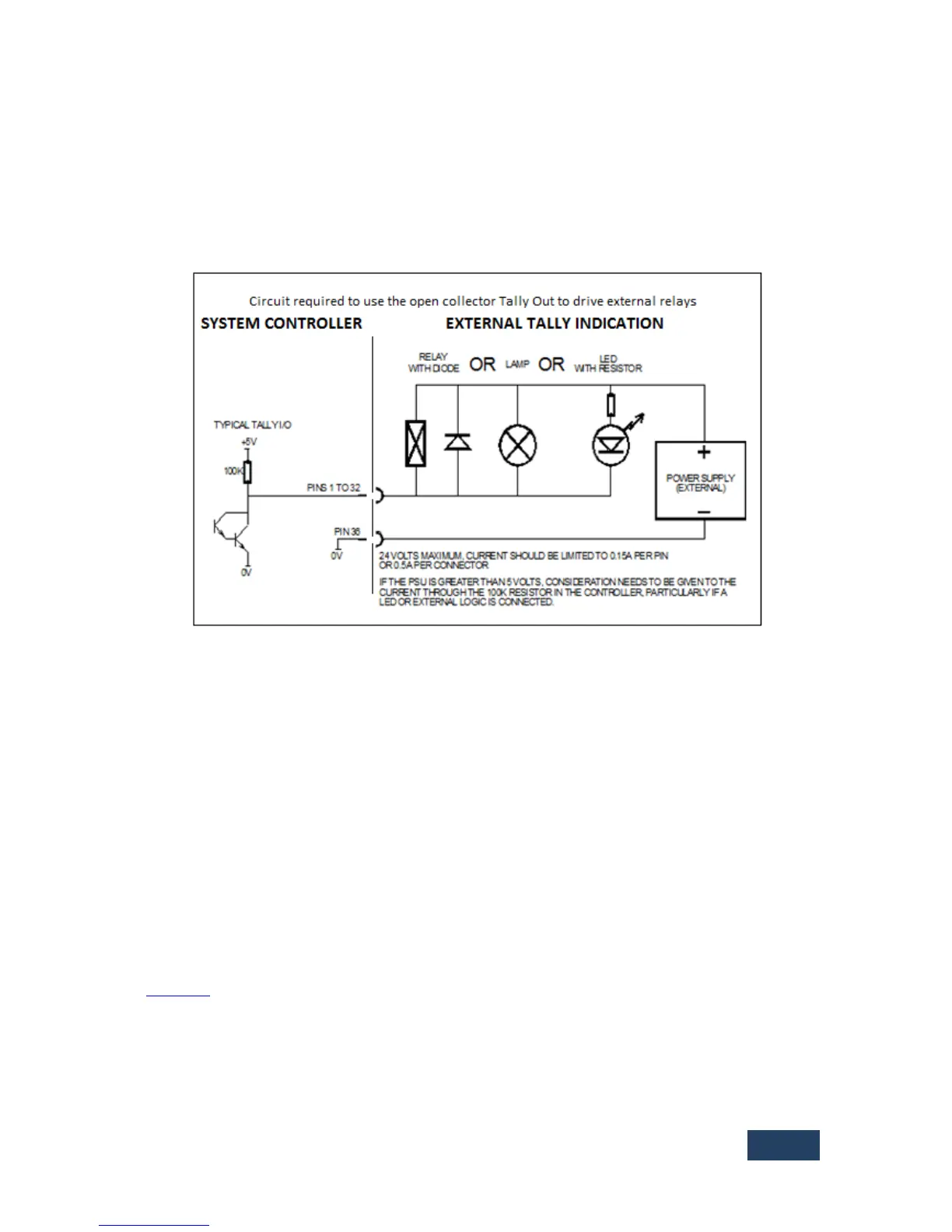
Tally outputs
Tally outputs consist of open collector driver circuits. Common (ground) appears on pin 36. The
circuit is capable of sinking approximately 150mAto ground to activate relays etc.
Notes:
1) Pin 34 carries a +12 V, or from Serial Number: 66200 +24V supply rated at 0.5A. Do not use
this internal +12V for relay coil supply.
2) Pin 35
LK1 on the internal EAB2 cards is set for the pull-up resistors to be referenced to normally + 5V or, by
changing the link to positions Centre/Ext, an external voltage reference applied to Pin 35 on the D37
connector.
If using an external voltage above 5V, the link on the card should be set for external pull-up (position
2-3, labelled EXT, away from the D37), and the external voltage should be applied to Pin 35. Putting
the link to EXT and applying the voltage to Pin 35 also enables the onboard spike suppression diodes.
Back to Top ^
 Loading...