state by pressing the Local key; however, the effect of this action will remain only until the
instrument is addressed again or receives another character from the ARC interface, when the
remote state will once again be entered.
ARC Interface
ARC Interface Connections
The 9-way D-type serial interface connector is located on the instrument rear panel. The pin
connections are as shown below:
Pin Name Description
1 - Power to optional PC-02
2 TXD Transmitted data from instrument
3 RXD Received data to instrument
4 - No internal connection
5 GND Signal ground
6 - No internal connection
7 RXD2 Secondary received data (see diagram)
8 TXD2 Secondary transmitted data (see diagram)
9 GND Signal ground
Pins 2, 3 and 5 may be used as a conventional RS232 interface with XON/XOFF handshaking.
Pins 7, 8 and 9 are additionally used when the instrument is connected to the ARC interface.
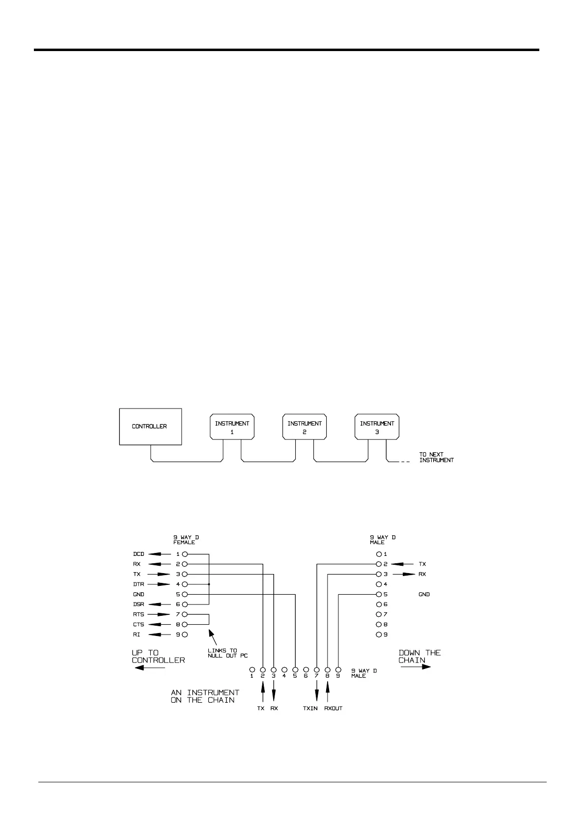
Using a simple cable assembly, a ‘daisy chain' connection system between any number of
instruments, up to the maximum of 32 can be made, as shown below:
The daisy chain consists of the transmit data (TXD), receive date (RXD) and signal ground lines
only. There are no control/handshake lines. This makes XON/XOFF protocol essential and allows
the inter-connection between instruments to contain just 3 wires. The wiring of the adaptor cable
is shown below:
All instruments on the interface must be set to the same baud rate and all must be powered on,
otherwise instruments further down the daisy chain will not receive any data or commands.
30
Telemeter Electronic GmbH | Joseph-Gaensler-Str. 10 | Phone +49 906 70693-0 | Fax +49 906 70693-50 | www.telemeter.info 31