Differential Gain Adjustment
Remove the link between the –OUTPUT and –SENSE terminals and fit a diode, anode to
–SENSE and cathode to –OUTPUT; connect a small switch across the diode. Leave the link in
place between +OUTPUT and +SENSE and connect a 15kΩ resistor between +OUTPUT and
–SENSE. Connect the DMM, set to Volts, between the sense terminals.
Close the switch, switch the output ON and set the output to approximately 17V; note the exact
reading. Open the switch and adjust VR4/VR104 for exactly the same reading; close the switch
again and check the reading is unchanged.
Remove the diode, resistor and switch and refit the sense link.
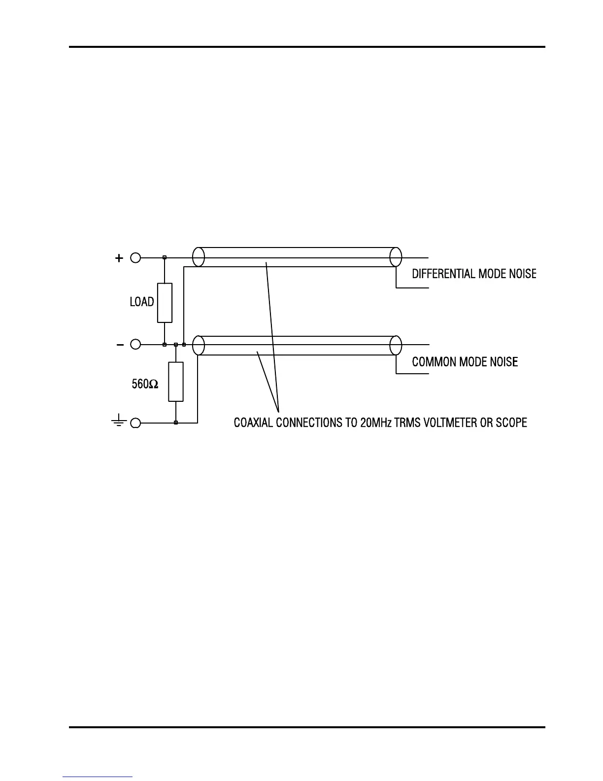
Noise Measurements
Differential and common-mode noise checks can be made using the arrangement below. Keep all
unscreened connections as short as possible.
Make measurements with the output fully loaded (e.g. 25V @ 7A). Measure differential and
common-mode noise one at a time on a 20MHz TRMS voltmeter or use a 20MHz bandwidth-
limited scope for peak-to-peak measurements.
13