Do you have a question about the TTI PL Series and is the answer not in the manual?
Defines the scope and applicability of the service manual for PL models.
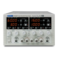
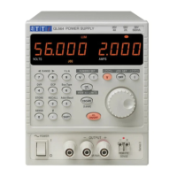
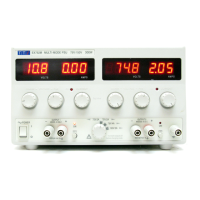
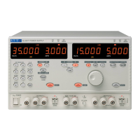
Provides an overview of the PL series power supplies and their features.
Instructions for safely disassembling the power supply unit for maintenance.
Details the specifications for the main output parameters of the power supplies.
Specifications for the 5V/7A logic output on PL330 QMT models.
Specifications for the 5V/4A logic output on PL320 QMT models.
Specifications for the 5V/1.5A logic output on PL310 QMT models.
Covers general power requirements, consumption, environmental ranges, weight, size, and compliance.
Instructions on checking and changing the mains operating voltage setting.
Guidance on connecting the mains lead correctly, including wiring and plug fitting.
Describes the main power supply section, including rectification and filtering.
Explains the auxiliary power supply for control and metering circuits.
Details the voltage control circuitry and adjustments.
Describes the constant current limiting and control mechanisms.
Explains the series regulator components and configuration.
Describes the Analog-to-Digital converter used for measurements.
Explains the role and operation of the microcontroller.
Explains the operation of the quad mode dual switchbank assembly.
Lists the necessary equipment for calibration.
Outlines the preparation steps before calibration.
General instructions for performing calibration.
Steps for calibrating the voltage differential gain.
Steps for calibrating the output voltage and meter.
Steps for calibrating the current settings and meter.
Calibration procedure for PL310/320 QMD/QMT models in quad mode.
Calibration procedure for PL330 QMD/QMT models in quad mode.
Functional description of the 5V/7A module for PL330 QMT.
Circuit description for the 5V/7A module, specifically for later PCB revisions.
Details the voltage control circuitry for the 5V/7A module.
Explains the current limiting and control for the 5V/7A module.
Describes the series regulator in the 5V/7A module.
Explains the over-voltage protection mechanism for the 5V/7A module.
Describes the ADC function for the 5V/7A module.
Explains the microcontroller's role in the 5V/7A module.
Lists equipment needed for 5V/7A module calibration.
Preparation steps for 5V/7A module calibration.
General calibration instructions for the 5V/7A module.
Steps for calibrating voltage differential gain on 5V/7A module.
Steps for calibrating output voltage and meter on 5V/7A module.
Steps for calibrating current on the 5V/7A module.
Circuit description for the 5V/4A module.
Describes the main power supply for the 5V/4A module.
Explains the auxiliary power supply for the 5V/4A module.
Details the voltage control circuitry for the 5V/4A module.
Explains the current control for the 5V/4A module.
Describes the over-voltage protection for the 5V/4A module.
Lists equipment needed for 5V/4A module calibration.
Steps for calibrating voltage differential gain on 5V/4A module.
Steps for calibrating output voltage on 5V/4A module.
Steps for calibrating current on the 5V/4A module.
Description of the 5V/1.5A circuit for PL310 QMT.
Lists fuse part numbers and ratings for different models and voltages.
Lists part numbers for power warning labels for various models.
Refers to schematics for system components.
Details configuration for specific revisions and switchbank types.
Details configuration for specific revisions and switchbank types.
| Brand | TTI |
|---|---|
| Model | PL Series |
| Category | Power Supply |
| Language | English |