Table of Contents
General 1
Specification 3
Installation 6
Functional Description – Main Outputs 9
Circuit Description – Main Outputs 10
Calibration – Main Outputs 12
Quad Mode Calibration 13
Quad Mode Triples 14
Funcitonal Description - 5V/7A Module (PL330 QMT) 14
Circuit Description - 5V/7A (Issue 2 PCBs and later) 14
Calibration - 5V/7A Module 17
Functional Description - 5V/4A Module (PL320QMT) 18
Circuit Description - 5V/4A 18
Calibration - 5V/4A 19
Circuit Description - 5V/1.5A (PL310QMT) 19
Parts List 20
Component Layouts & Circuit Diagrams 38
General
Applicability of this Manual
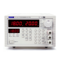
This Service Manual is for the revised PL models introduced from mid-1991, with the exception of
the PL-P 3Amp programmable models which are covered by a separate manual. The revised PLs
differ substantially in their circuit configurations from their predecessors whilst functionally
remaining very similar; the new models can, however, be very easily distinguished from the
earlier series because they have a push-button current damping switch instead of a panel-
mounted rocker switch. The earlier PLs are covered by separate manuals for the manual and
programmable versions.
Introduction
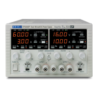
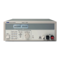
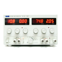
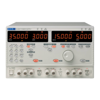
The PL series of power supplies are fully variable series regulated units incorporating separate
digital meters for voltage and current. Separate voltage and current control circuits enable them
to operate in constant voltage or constant current mode from 0 to 32 Volts at 0 to 1.1 Amps, 2.1
Amps or 3.1 Amps (0 to 15 Volts at 4 Amps - PL154); triple versions have additional 5 Volt logic
supply outputs.
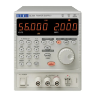
In addition to the AC input switch, there is a DC output switch. When this switch is 'off', the +ve
output is disconnected and the current meter reads the value of the current control setting. The
current meter decimal points are used to indicate the mode as follows:
Decimal points off - output switch 'on', constant voltage operation, meter reading output current.
Decimal points on - output switch 'off', meter reading current limit setting
Decimal points flashing - output switch 'on' constant current operation, meter reading output current.
1