4. Description of Frequency Determining and Stabilizing Circuit
4-1. Introduction
The Frequencies for transmitter and receiver first local frequencies are all derived from a signal
4.5MHz crystal by means of a phase locked loop(PLL).
The first local oscillator frequencies are 16.270MHz(CH1) to 16.710MHz(CH40). The second local
frequency is fixed at 10.240MHz to generate second IF 455KHz.
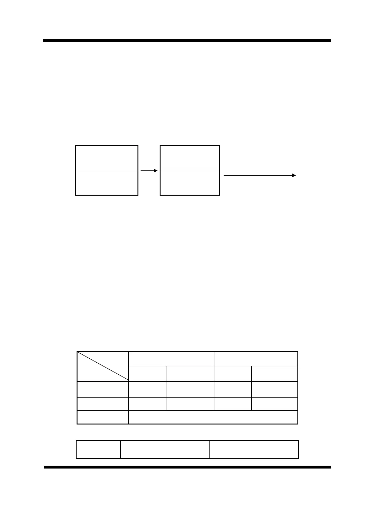
Transmit, the VCO of the PLL operates 13.4825MHz(CH1) to 13.7025MHz(40CH). The VCO frequency
goes to the doublers circuit Q701, L701, L702 with doubles the frequency to generate 26.965MHz(CH1)
to 27.405MHz(40CH).
Q302
VCO
Q701
Doublers
13.4825MHz(CH1)
~
13.7025MHz(CH40)
26.965MHz(CH1)
~
27.405MHz(CH40)
To transmitter
The VCO operating frequency for the receiver is 16.27MHz(CH1) to 16.710MHz(CH40) as the
first local oscillator, injected through the buffer amplifier Q302 into the first FET balanced mixer Q102,
Q103.
4-2. Basic Synthesis Scheme
The crystal frequency(4.5MHz) is divided by 1800 times to make 2.5KHz which is fed to one
side of the phase detector. The VCO output is divided by a programmable divider, and fed to other side of
the phase detector Pin 9, 10 of IC301. Passing the phase detector output closes the feedback loop through
an active low pass filter and using the output to control the VCO frequency through varicap diode D301.
Under locked conditions, both of phase detector input signal must be identical at 2.5KHz.
The VCO frequency is then given by ;
Receiver : Fvco / N = 0.005 [MHz] OR Fvco = 0.005 X N [MHz]
Transmitter : Fvco / N = 0.0025 [MHz] OR Fvco = 0.0025 X N [MHz]
Since “N” is an integer, the VCO frequency can be stepped up with in receiver mode 5KHz and
transmitter mode 2.5KHz increments.
By suitable choice of “N” the desired output frequency can be obtained.
Channel 1 Channel 40
N Fvco N Fvco
Transmit 5393 13.4825 5481 13.7025
Receiver 3254 16.2700 3342 16.7100
See the [Table 1]for other Channels
The VCO frequency goes to the doublers circuit, with doubles the incoming signals.
VCO Output Frequency Doublers Output Frequency