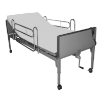
4-1, For T2010 – Continued from Step 2, pull to release the cotter pin from the clevis holding
pin. Align the drive shaft hole with the holes on the lifting plate. Re-secure the holding pin on
both sides of the left plate. Then reattach the cotter pin to lock.
Repeat on Head Section.
Figure 4 -1 Figure 4-1
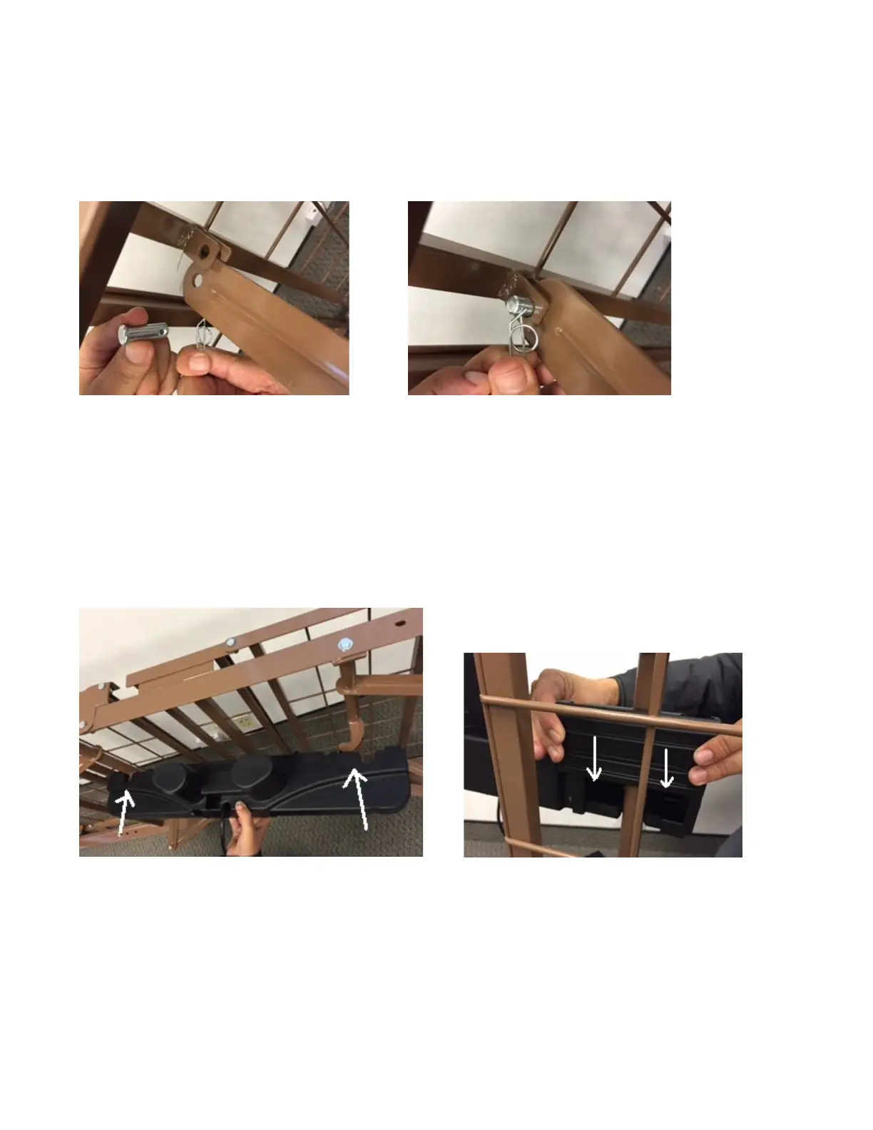
4-2, For T2010 – Installation of Motor and Hand Pen with bed frame:
A1, Slide locking covers (Foot and head section) out of motor.
A2, Align the opening on the head end of the motor with the flange on the head section of the
bed and insert the flange into the motor compartment. Then, with the palm of your hand, snap
the motor flush to the actuator bar.
Repeat on Foot Section.
Figure A-2 Figure A-3
A3, After the motor is installed, slide locking covers back on motor.
-7-