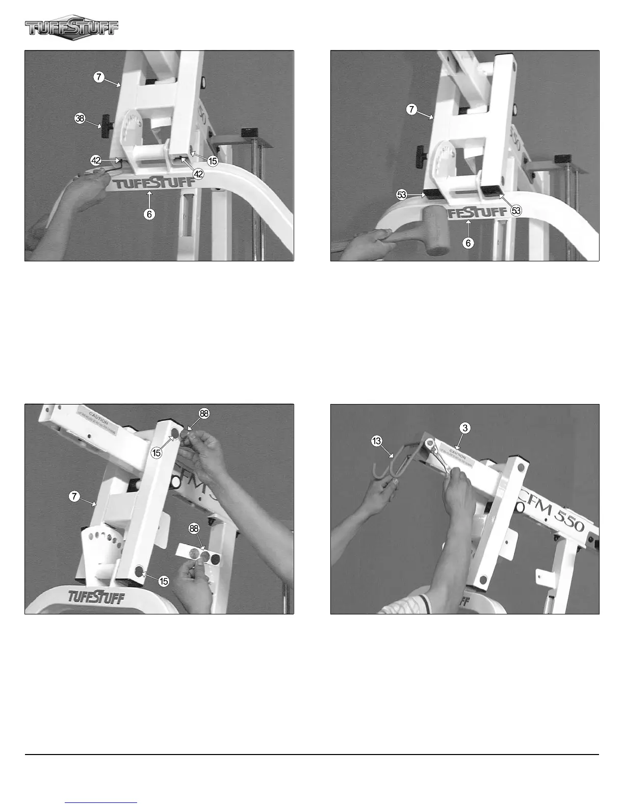
FIG. 31 Attach the Lat Bar Holder (#13), in the position as shown
above, to the Top Pulley Housing (#3) and secure it into place using one
Hex Head Cap Screw 3/8-16 X 2-3/4 (#75), two Flat Washers SAE
3/8” (#60), and one Nylon Insert Jam Lock Nut 3/8-16 (#68).
Fig. 29 Next, using a rubber mallet, insert two Plastic Insert Caps 2 Sq.
(#53) into the tube-ends of the Press Bar Selector Housing (#7), as
shown above.
FIG. 30 Next, apply a 1" Rd. Silver Mylar Decal (#88) over each end of
the two Pivot Axles (#15). These Decals are used to hide and protect the
ends of the Pivot Axles (#15).
CFM-550 Compact Frontal Machine
9
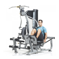
FIG. 28 Secure the Press Bar (#6) into the Press Bar Selector Hous-
ing (#7) by threading the two Set Screws 1/4-20 X 3/8 (#42), located on
Press Bar Selector Housing (#7), against the Pivot Axle (#15) using the
supplied Hex Key 1/8” (#86).