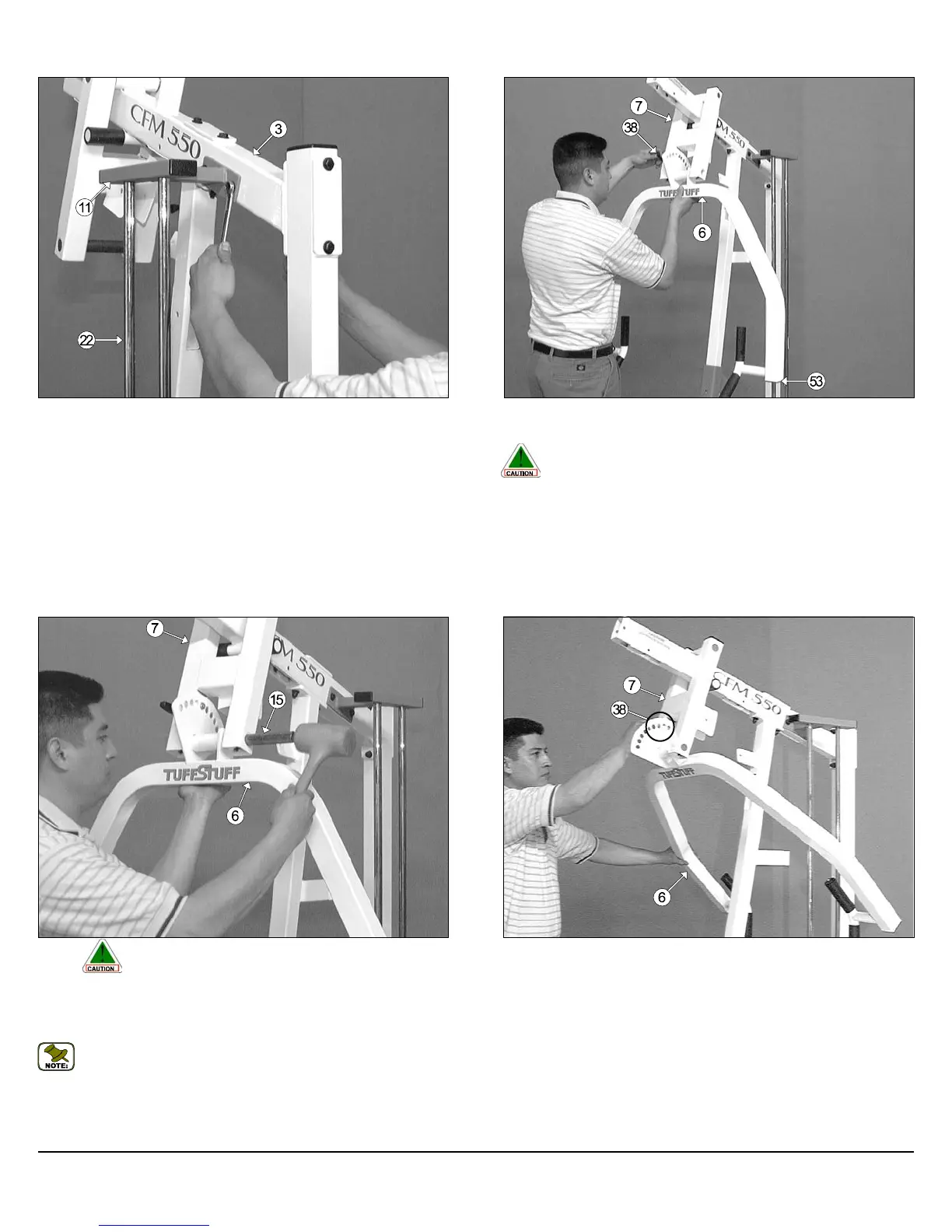
FIG. 25 Next, using a rubber mallet, insert two Plastic Insert Caps 2"
Sq. (#53-Not shown) into the tube-ends of the Press Bar (#6).
Caution: It is recommended to use another person in assisting
with this assembly.
Insert the Press Bar (#6) up into the Press Bar Selector Housing (#7)
and support it into place using the Push-Pull Pin 1/2 X 3-1/2 (#38), as
shown above.
FIG. 26 Caution: It is recommended to use another person in as-
sisting with this assembly.
Insert a Pivot Axle 1 X 8-1/8 (#15) into the Press Bar Selector Housing
(#7) and through the Press Arm (#6) until it becomes flush with both sides
of the Press Bar Selector Housing (#7).
Note: It is recommended to grease the Pivot Axle 1 X 8-1/8 (#15)
with multi-purpose grease prior to assembling.
FIG. 27 Adjust the Press Bar (#6) to the far back Press Bar Setting, as
shown above, and release the Push-Pull Pin 1/2 X 3-1/3 (#38) to lock the
Press Bar (#6) into this position.
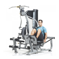
FIG. 24 Mount the Guide Rod Retainer Housing (#11) along with the
two captive Guide Rods (#22) to the side of the Top Pulley Housing
(#3), as shown above, and secure them into place using two Hex Head
Cap Screws 3/8-16 X 3-1/4 (#76), four Flat Washers SAE 3/8” (#60), and
two Nylon Insert Lock Nuts 3/8-16 (#69).
8
CFM-550 Compact Frontal Machine
Owner’s Manual: Assembly Instructions