FIG. 38 Next, install one Nylon Pulley 4-1/2 Rd (#45-Labeled D) onto
the pulley plate located on the Front Upright (#5), in the position as
shown above, and secure it into place using one Hex Head Cap Screw
3/8-16 X 1-3/4 (#73), two Flat Washers SAE 3/8” (#60), one Cable
Retainer Bracket (#20), and one Nylon Insert Jam Lock Nut 3/8-16 (#68).
Note: Be sure to position the Cable Retainer Bracket (#20) as
shown above.
Next, insert one Nylon Pulley 4-1/2 Rd. (#45-Labeled F) into the slot lo-
cated on the Front Upright (#5) and secure it into place using one Hex
Head Cap Screw 3/8-16 X 2-1/2 (#74), two Flat Washers SAE 3/8” (#60),
and one Nylon Insert Jam Lock Nut 3/8-16 (#68).
FIG. 37 Install two Nylon Pulleys 4-1/2 Rd. (#45-Labeled C, E) into the
pulley bracket located on the Press Bar Selector Housing (#7) and
secure them into place using one Hex Head Cap Screw 3/8-16 X 2-3/4
(#75), two Flat Washers SAE 3/8” (#60), and one Nylon Insert Jam Lock
Nut 3/8-16 (#68).
Fig. 39 Assemble the Adjustable Double Pulley Bracket (#16) using
two Nylon Pulleys 4-1/2 Rd. (#45-Labeled G, K), two Hex Head Cap
Screws 3/8-16 X 1-3/4 (#73), four Flat Washers SAE 3/8” (#60), and two
Nylon Insert Jam Lock Nuts 3/8-16 (#68).
Note: The four holes on the Adjustable Double Pulley Bracket
(#16) are used to adjust the cable tension once the cable routing
has been completed.
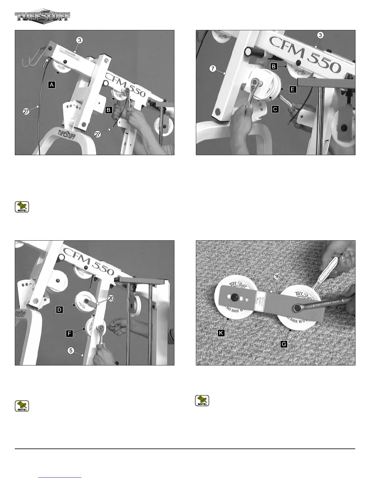
FIG. 36 Next, route the end of the Lat Cable (#27) through the opening
located at the bottom of the Top Pulley Housing (#3). Then insert a
Nylon Pulley 4-1/2 Rd. (#45-Labeled B) into this slot and secure the Nylon
Pulley 4-1/2 Rd. (#45-Labeled B) into place using one Hex Head Cap
Screw 3/8-16 X 2-1/2 (#74), two Flat Washers SAE 3/8” (#60), and one
Nylon Insert Jam Lock Nut 3/8-16 (#68). Be sure the cable is routed prop-
erly into the groove on the Nylon Pulley 4-1/2 Rd. (#45-Labeled B).
Note: Use Cable Mapping Diagram on page 20 for further detailed
illustration of the Lat Cable (#27) routing.
CFM-550 Compact Frontal Machine
11