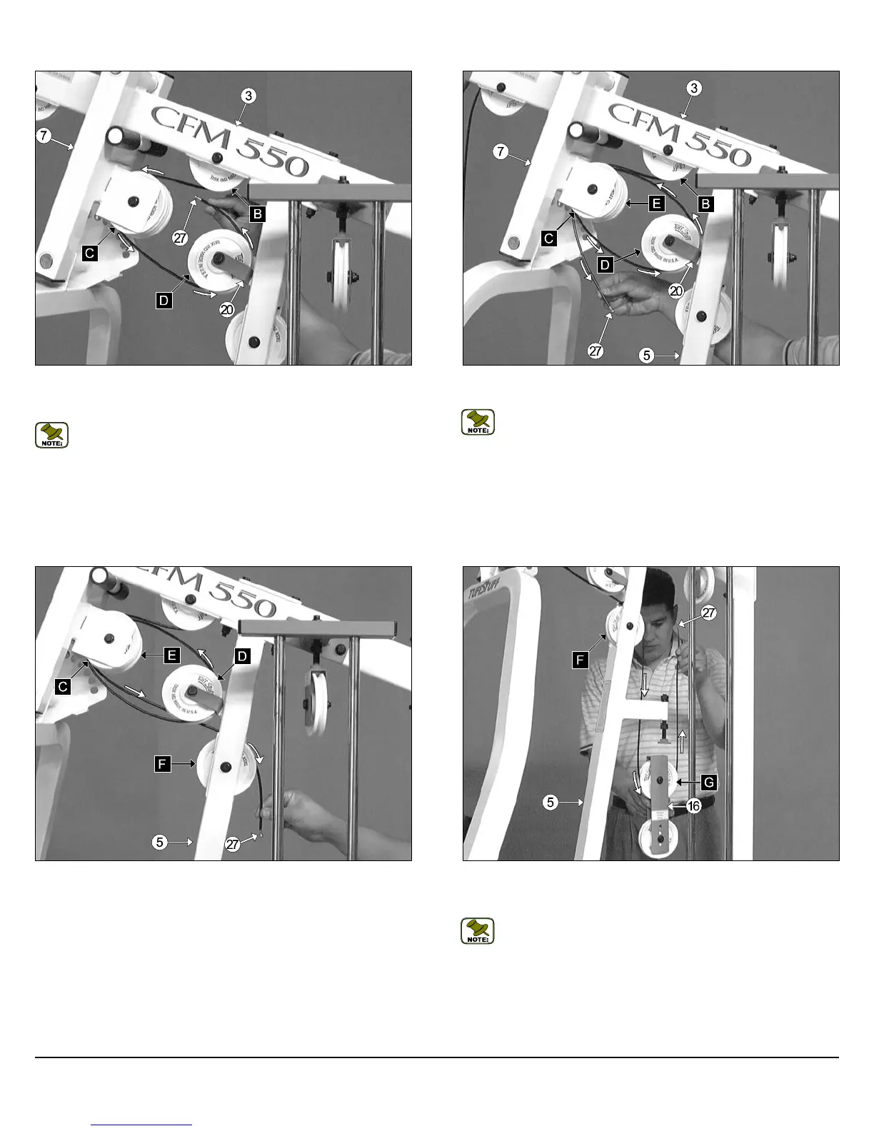
FIG. 42 Next, route the Lat Cable (#27) through the Front Upright
(#5) and over the Nylon Pulley 4-1/2 Rd. (#45-Labeled F), as shown.
FIG. 43 Next, route the Lat Cable (#27) through the Adjustable Dou-
ble Pulley Bracket (#16) and under the Nylon Pulley 4 1/2 Rd. (#45-
Labeled G), as shown above.
Note: Use Cable Mapping Diagram on page 20 for further detailed
illustration of the Lat Cable (#27) routing.
12
CFM-550 Compact Frontal Machine
FIG. 40 Next, route the Lat Cable (#27) over the Nylon Pulley 4-1/2
Rd. (#45-Labeled C), then up and over the Nylon Pulley 4-1/2 Rd. (#45-
Labeled D).
Note: Use Cable Mapping Diagram on page 20 for further detailed
illustration of the Lat Cable (#27) routing.
FIG. 41 Next, route the Lat Cable (#27) over the Nylon Pulley 4-1/2
Rd. (#45-Labeled E), as shown above.
Note: Use Cable Mapping Diagram on page 20 for further detailed
illustration of the Lat Cable (#27) routing.
Owner’s Manual: Assembly Instructions