FIG. 46 Next, install a Nylon Pulley 4-1/2 Rd. (#45-Labeled I) into the
pulley bracket located on the Leg Extension Arm (#8) and secure it into
place using one Hex Head Cap Screw 3/8-16 X 1-3/4 (#73), two Flat
Washers SAE 3/8” (#60), and one Nylon Insert Jam Lock Nut 3/8-16
(#68). Next, route the Leg Extension Cable (#28) under the Nylon Pulley
4-1/2 Rd. (#45-Labeled I), then secure it into place using one Hex Head
Cap Screw 1/4-20 X 1-1/2 (#63), and one Nylon Insert Lock Nut 1/4-20
(#64).
Note: Refer to Fig. C on page 20 for further illustration of this
assembly.
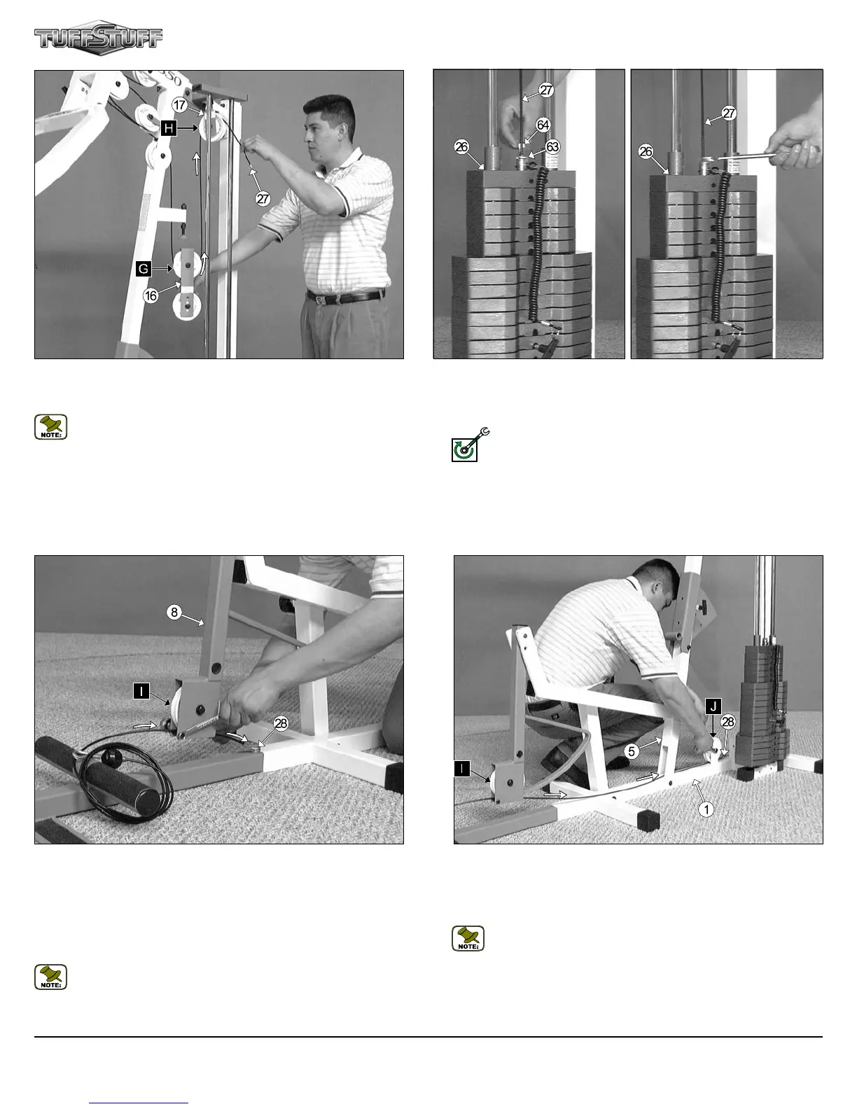
FIG. 45 Next, attach the Lat Cable (#27) to the Top Plate/ Selector
Bar (#26) and secure it into place using one Split Bolt 1/2-13 (#64), and
one Split Washer 1/2” (#63). Refer to Fig. B on page 20 for further
illustration of this hardware assembly.
Fully Fasten: Proceed to fully fasten this hardware assembly.
FIG. 44 Next, route the Lat Cable (#27) through the Adjustable Pulley
Bracket (#17) and over the Nylon Pulley 4 1/2 Rd. (#45-Labeled H), as
shown above.
Note: Use Cable Mapping Diagram on page 20 for further detailed
illustration of the Lat Cable (#27) routing.
FIG. 47 Next, route the Leg Extension Cable (#28) through the Front
Upright (#5), then under the Nylon Pulley 4-1/2 Rd. (#45-Labeled J).
Secure the Nylon Pulley 4-1/2 Rd. (#45-Labeled J) into place using one
Hex Head Cap Screw 3/8-16 X 1-3/4 (#73), two Flat Washers SAE
3/8” (#60), and one Nylon Insert Jam Lock Nut 3/8-16 (#68).
Note: Use Cable Mapping Diagram on page 20 for further detailed
illustration of the Leg Extension Cable (#28) routing.
FULLY FASTEN
CFM-550 Compact Frontal Machine
13