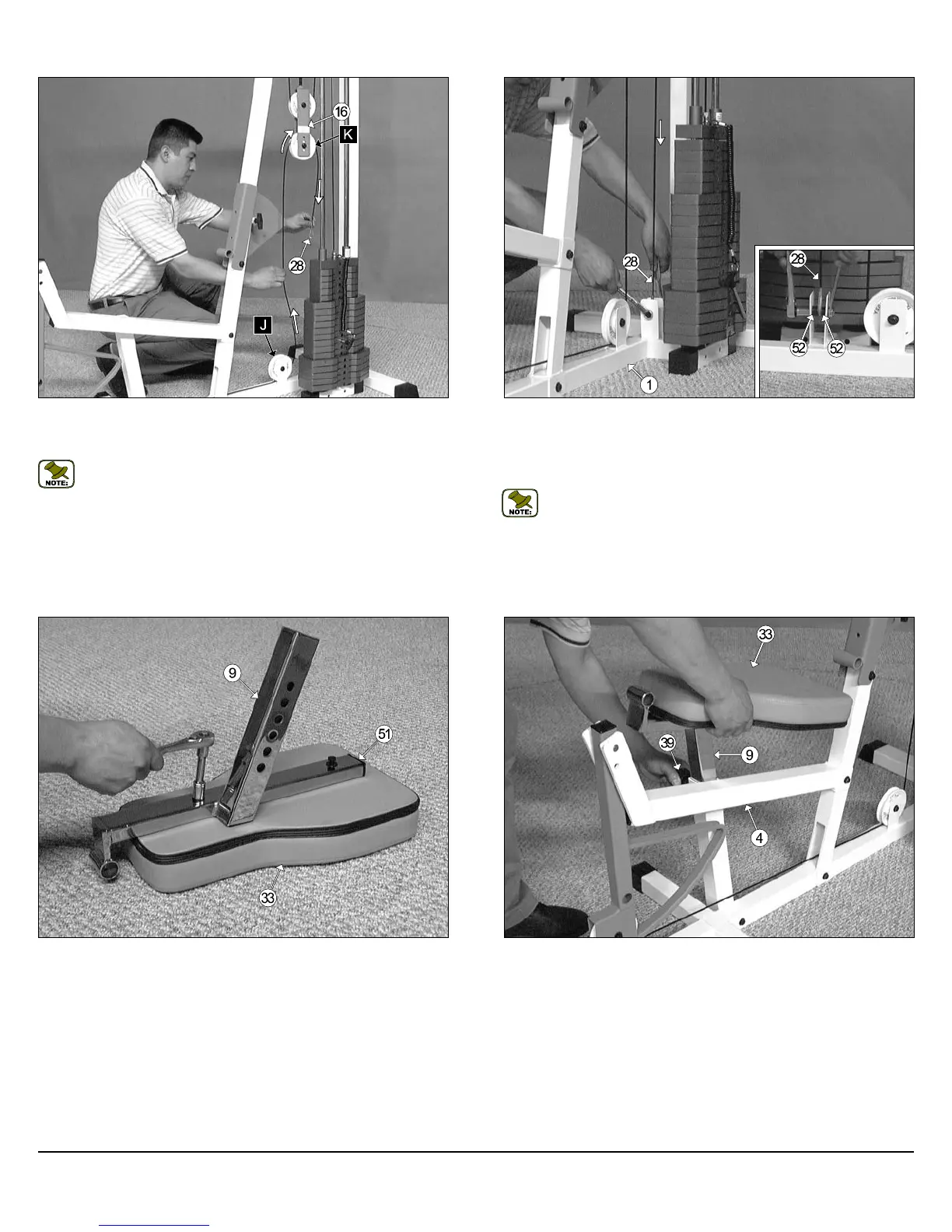
FIG. 51 Insert the Bench Press Adj. Seat Frame (#9) into the Leg Ex-
tension Bench Frame (#4), in the position as shown above. Be sure to
release the Turn/Pull Pin w/Knob (#39) as you begin to insert the assem-
bled Bench Press Adj. Seat Frame (#9) into the Leg Extension Bench
Frame (#4).
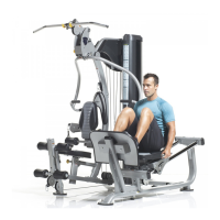
FIG. 48 Lift the end of the Leg Extension Cable (#28) and route it
through the Adjustable Double Pulley Bracket (#16) and over the Nylon
Pulley 4-1/2 Rd. (#45-Labeled K), as shown above.
Note: Use Cable Mapping Diagram on page 20 for further detailed
illustration of the Leg Extension Cable (#28) routing.
FIG. 50 Next, using a rubber mallet, insert one Plastic Insert Cap 1 X 2
(#51) into the tube-end of the Bench Press Adj. Seat Frame (#9). Next,
locate the Seat Pad (#33) and attach it to the Bench Press Adj. Seat
Frame (#9), as shown above, using two Hex Head Cap Screws 3/8-16 X
1-3/4 (#73), and two Flat Washers SAE 3/8” (#60).
FIG. 49 Connect the looped end of the Leg Extension Cable (#28) to
the pulley bracket located on the Base Frame (#1), as shown above.
Secure this assembly using one Hex Head Cap Screw 3/8-16 X 1-3/4
(#73), two Flat Washers SAE 3/8” (#60), two Nylon Spacers 3/8 X 3/8
(#52), and one Nylon Insert Jam Lock Nut 3/8-16 (#68).
Note: Refer to Fig. D on page 20 for further illustration of this
assembly.
14
CFM-550 Compact Frontal Machine
Owner’s Manual: Assembly Instructions