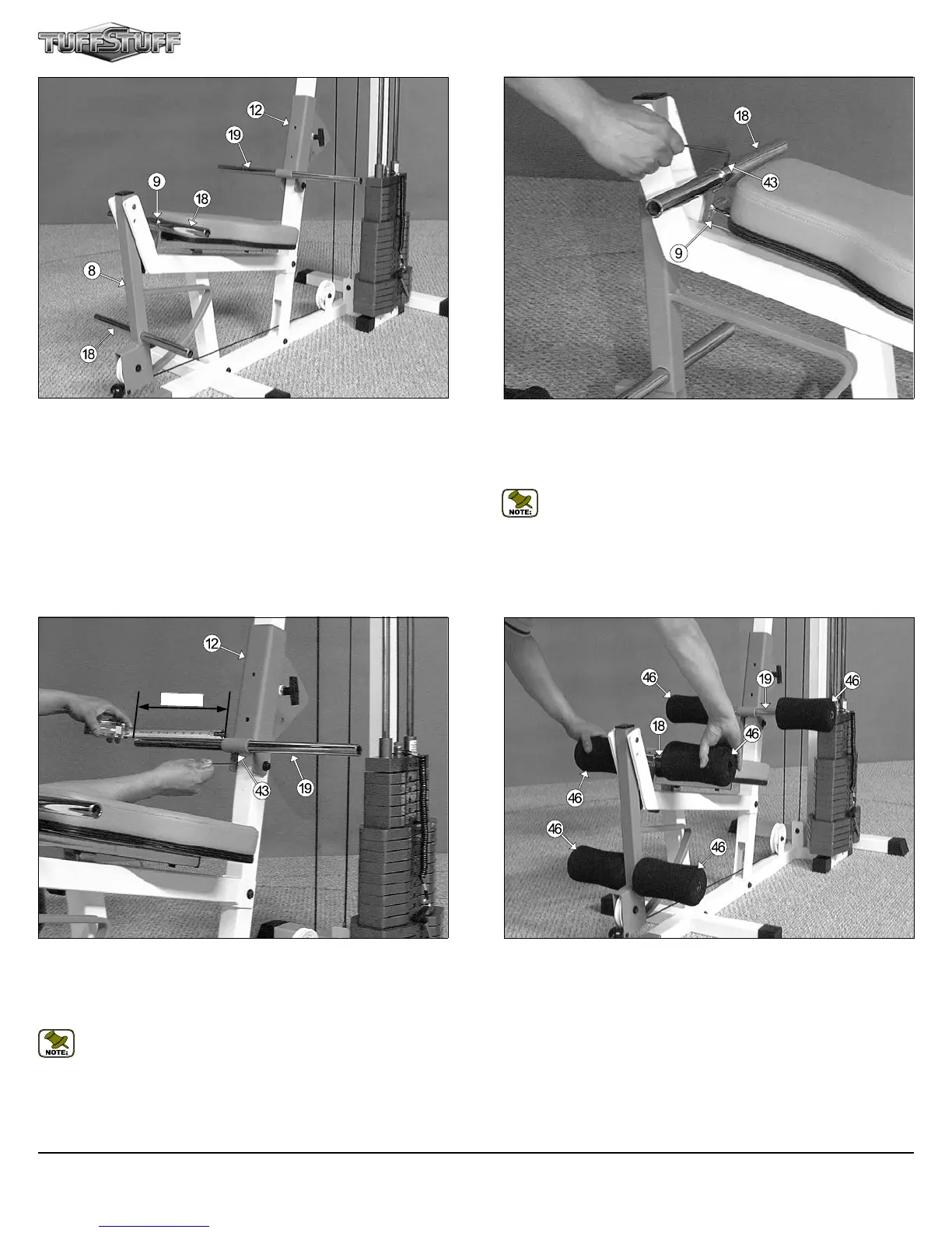
FIG. 53 Secure the Foot Roll Tube 1 X 16 (#18) to the Bench Press
Adj. Seat Frame (#9) using a Set Screw 1/4-20 X 1/4 (#43). Use the
supplied Hex Key 1/8” (#86) for securing the Set Screw 1/4-20 X 1/4 (#43)
into the threaded socket located on the Bench Press Adj. Seat Frame
(#9).
Note: Refer to Fig. 67 on page 19 for further illustration of this
assembly.
FIG. 55 insert one Foam Foot Roll 7 X 4 X 1 (#46) onto each end of
the three Foot Roll Tubes, as shown above. Refer to the Exploded View
Diagram on page 21 for further clarification of this assembly.
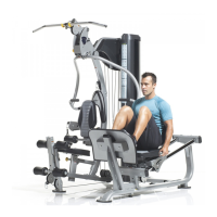
FIG. 52 Next, insert one Foot Roll Tube 1 X 16 (#18) into the recepta-
cle located on the Bench Press Adj. Seat Frame (#9). Then, insert the
other Foot Roll Tube 1 X 16 (#18) into the receptacle located on the Leg
Extension Arm (#8). Next, insert the Foot Roll Tube 1 X 23-3/4 (#19)
into the receptacle located on the Adjustable Back Pad Bracket (#12),
as shown above. Be sure all these tubes are centered at the receptacles
from end-to-end.
CFM-550 Compact Frontal Machine
15
FIG. 54 Secure the Foot Roll Tube 1 X 23-3/4 (#19) to the Adjustable
Back Pad Bracket (#12) using a Set Screw 1/4-20 X 1/4 (#43). Use the
supplied Hex Key 1/8” (#86) for securing the Set Screw 1/4-20 X 1/4 (#43)
into the threaded socket located on the Adjustable Back Pad Bracket
(#12).
Note: Refer to Fig. 68 on page 19 for further illustration of this
assembly. In addition, a measuring tape is used to center the Foot
Roll Tube 1 X 23-3/4 (#19). The measurement from one end of the
tube to the receptacle, as pictured above, should be about 10-1/2”.
10
-
1/2”