FIG. 57 Mount the Back Pad (#32) to the Back Pad Bracket (#12) and
secure into place using two Hex Head Cap Screws 3/8-16 X 1-1/4 (#72),
and two Steel Bumper Washers 3/8” (#59). Cap-off the two Steel Bumper
Washers 3/8” (#59-Not shown) using two Bumper Caps (#58).
Note: Refer to Fig. 69 on page 19 for further clarification of this
assembly.
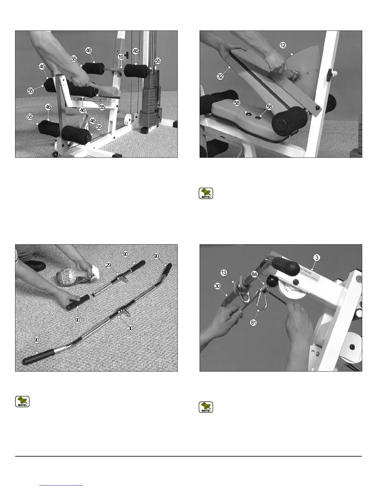
FIG. 58 Insert one Rubber Grip 1 X 6 (#90) over each one of the tube-
ends of Low Row Bar 20” (#29) and the Lat Bar 48” (#30), as shown
above.
Note: To facilitate the insertion of these Rubber Grips, use Windex
or household glass cleaner.
FIG. 59 Next, attach a Snap Link (#81) to the Lat Cable (#27) and se-
cure it into place using one Shoulder Bolt 3/8 X 3/4 (#82), and one Nylon
Insert Lock Nut 5/16-18 (#67). Use the supplied Hex Key 3/16” (#85) and
a 1/2” combination wrench to fasten this assembly properly.
Note: Refer to Fig. A on page 20 for further illustration of this
assembly.
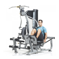
FIG. 56 Next, using a rubber mallet, insert one Foot Roll Plastic End
Cap 1” (#55) into each end of the three Foot Roll Tubes, as shown
above. Refer to the Exploded View Diagram on page 21 for further clarifi-
cation of this assembly.
16
CFM-550 Compact Frontal Machine
Owner’s Manual: Assembly Instructions