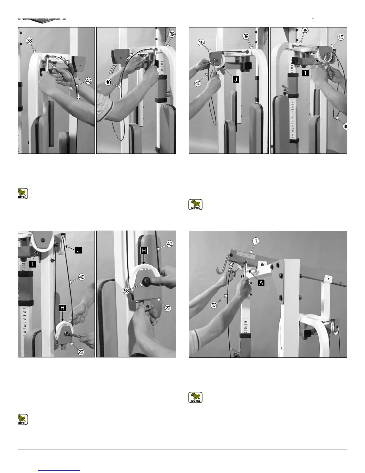
Fig. 28 Insert the Lat Cable (#53) and a Nylon Pulley 4 1/2” Rd. (#2
Labeled A) into the pulley bracket located on the Top Pulley Housing (#1
as shown, then secure the Nylon Pulley 4 1/2” Rd. (#20-Labeled A) in
place using one Hex Head Cap Screw 3/8-16 X 2 1/2 (#29), two Flat Was
ers SAE 3/8” (#45), and one Nylon Insert Jam Lock Nut 3/8-16 (#46).
Note: Refer to the Cable Mapping Diagram on page 18 for furth
clarification of the Lat Cable (#53) routing.
Fig. 26 Next, insert the Pec Dec Cable (#40) through the pulley brack
on the Pec Dec Housing (#15) and install one Nylon Pulley 4 1/2” Rd. (#2
Labeled J). Secure it into place using one Hex Head Cap Screw 3/8-16 X
3/4 (#30), two Flat Washers SAE 3/8” (#45), and one Nylon Insert Jam Lo
Nut 3/8-16 (#46). Repeat the same procedure to route and secure the P
Dec Cable (#40) through the pulley bracket on the opposite side of the P
Dec Housing (#15).
Note: The black boxed letters pointing to the pulleys are us
throughout this manual as reference to the Cable Mapping Diagra
on page 18 These black boxed letters will be primarily used for loc
ing certain pulleys during the cable routing process beginning wi
Fig. 26.
g. 25 Begin routing the Pec Dec Cable (#40) by attaching it to the Pec
ec Arm Rt. (#38) using one Hex Head Cap Screw 3/8-16 X 1 (#47), two
at Washers SAE 3/8” (#45), and one Nylon Insert Jam Lock Nut 3/8-16
46). Repeat the same procedure to attach the Pec Dec Cable (#40) to
e Pec Dec Arm Lt. (#38).
Note: Refer to the Cable Mapping Diagram on page 18 for further
clarification of the Pec Dec Cable (#40) routing.
g. 27 Next, insert one Nylon Pulley 4 1/2” Rd. (#20-Labeled H) and the
c Dec Cable (#40) into the Pec Dec Floating Pulley Bracket (#22) and
cure them into place using one Hex Head Cap Screw 3/8-16 X 1 1/2
70), two Steel Bumper Washers 3/8” (#58), and one Nylon Insert Jam
ck Nut 3/8-16 (#46).
ext, snap one Plastic Bumper End Cap (#57) over each Steel Bumper
asher 3/8” (#58). Place the Plastic Bumper End Cap (#57) over one edge
the Steel Bumper Washer 3/8” (#58) and use gentle pressure with the
umb to snap the Plastic Bumper End Cap (#57) into place.
Note: Refer to the Exploded View Diagram and Cable Mapping Dia-
gram on page 18 for further clarification of this assembly.
9
TDH 345 Half Cage Ensembl