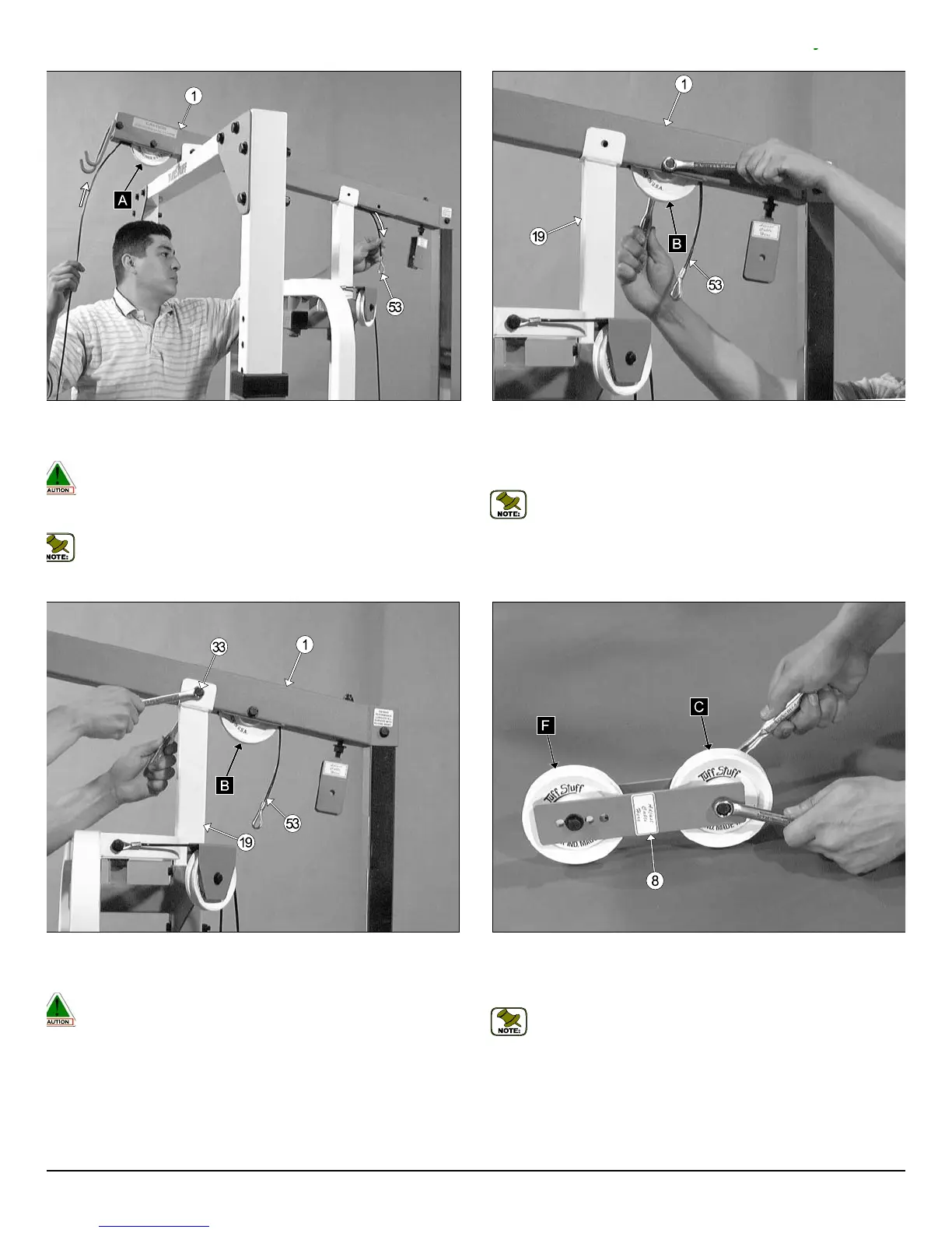
ig. 29 Route the end of the Lat Cable (#53) through the Top Pulley
ousing (#1) tube. Next, pull gently the Lat Cable (#53) down through the
ot on the bottom side of the Top Pulley Housing (#1).
Caution: Do not pull the Lat Cable (#53) all the way through the Top
Pulley Housing (#1) until you have installed the Nylon Pulley 4 1/2”
Rd. (#20-Labeled B), as this will prevent any damage to the Cable.
See Fig. 30.
Note: Refer to the Cable Mapping Diagram on page 18 for further
detailed illustration of the Lat Cable (#53) routing.
Fig. 30 Insert one Nylon Pulley 4 1/2” Rd. (#20-Labeled B) into the slot
the Top Pulley Housing (#1), in the position as shown above, and secure
into place using one Hex Head Cap Screw 3/8-16 X 2 1/2 (#29), two Fl
Washers SAE 3/8” (#45), and one Nylon Insert Jam Lock Nut 3/8-16 (#46
Be sure the Lat Cable (#53) is routed properly into the pulley’s groove.
Note: Refer to the Cable Mapping Diagram on page 18 for furth
detailed illustration of the Lat Cable (#53) routing.
ig. 31 Secure the Top Pulley Housing (#1) to the Center Upright (#19)
ing one Hex Head Cap Screw 3/8-16 X 2 3/4 (#33), two Flat Washers
AE 3/8” (#45), and one Nylon Insert Jam Lock Nut 3/8-16 (#46).
Caution: To prevent damage to the Lat Cable (#53), it is important to
make sure that the Lat Cable (#53) is routed over the top, and not
under the Hex Head Cap Screw 3/8-16 X 2 3/4 (#33).
Fig. 32 Assemble the two Double Pulley Plates (#21) using two Nylo
Pulleys 4 1/2” Rd. (#20-Labeled C and F), two Hex Head Cap Screws 3/
16 X 1 3/4 (#30), four Flat Washers SAE 3/8” (#45), and two Nylon Inse
Jam Lock Nuts 3/8-16 (#46).
Note: The four holes on the Double Pulley Plates (#21) are used
adjust the cable tension once the cable routing has been completed.
TDH 345 Half Cage Ensemble
10
y