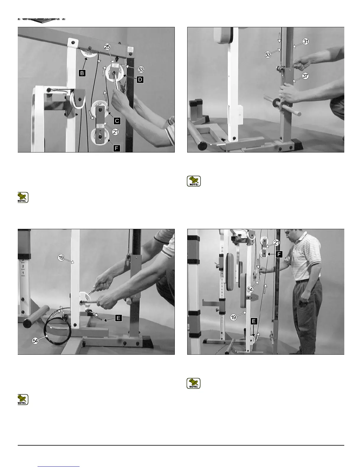
Fig. 34 Next, route the Lat Cable (#53) down and secure the looped e
to the bracket on the Weight Carriage (#37) using one Hex Head C
Screw 3/8-16 X 1 (#47), and one Nylon Insert Jam Lock Nut 3/8-16 (#46).
Note: Refer to Fig. B on page 18 for further illustration of this asse
bly.
ig. 33 Route the Lat Cable (#53) through the Double Pulley Plates
21) and under the Nylon Pulley 4 1/2” Rd. (#20-Labeled C). Next, insert
e Cable and one Nylon Pulley 4 1/2” Rd. (#25-Labeled D) into the Upper
wivel Bracket (#25), in the position as shown above. Secure the Pulley
to place using one Hex Head Cap Screw 3/8-16 X 1 3/4 (#30), two Flat
ashers SAE 3/8” (#45), and one Nylon Insert Jam Lock Nut 3/8-16 (#46).
Note: Refer to the Cable Mapping Diagram on page 18 for further
detailed illustration of the Lat Cable (#53) routing.
ig. 35 Route the Low Row Cable (#54) through the Center Upright’s
19) pulley bracket, then insert one Nylon Pulley 4 1/2” Rd. (#20-Labeled
) into the Center Upright’s (#19) pulley bracket and secure it into place
ing one Hex Head Cap Screw 3/8-16 X 1 3/4 (#30), two Flat Washers
AE 3/8” (#45), and one Nylon Insert Jam Lock Nut 3/8-16 (#46). Be sure
e Low Row Cable (#54) is routed properly into the pulley’s groove.
Note: Refer to the Cable Mapping Diagram on page 18 for further
detailed illustration of the Low Row Cable (#54) routing.
Fig. 36 Continue routing the Low Row Cable (#54) up and over the N
lon Pulley 4 1/2” Rd. (#20-Labeled F) and through the Double Pulley Plate
(#21), as shown above.
Note: Refer to the Cable Mapping Diagram on page 18 for furth
detailed illustration of the Low Row Cable (#54) routing.
11
TDH 345 Half Cage Ensembl