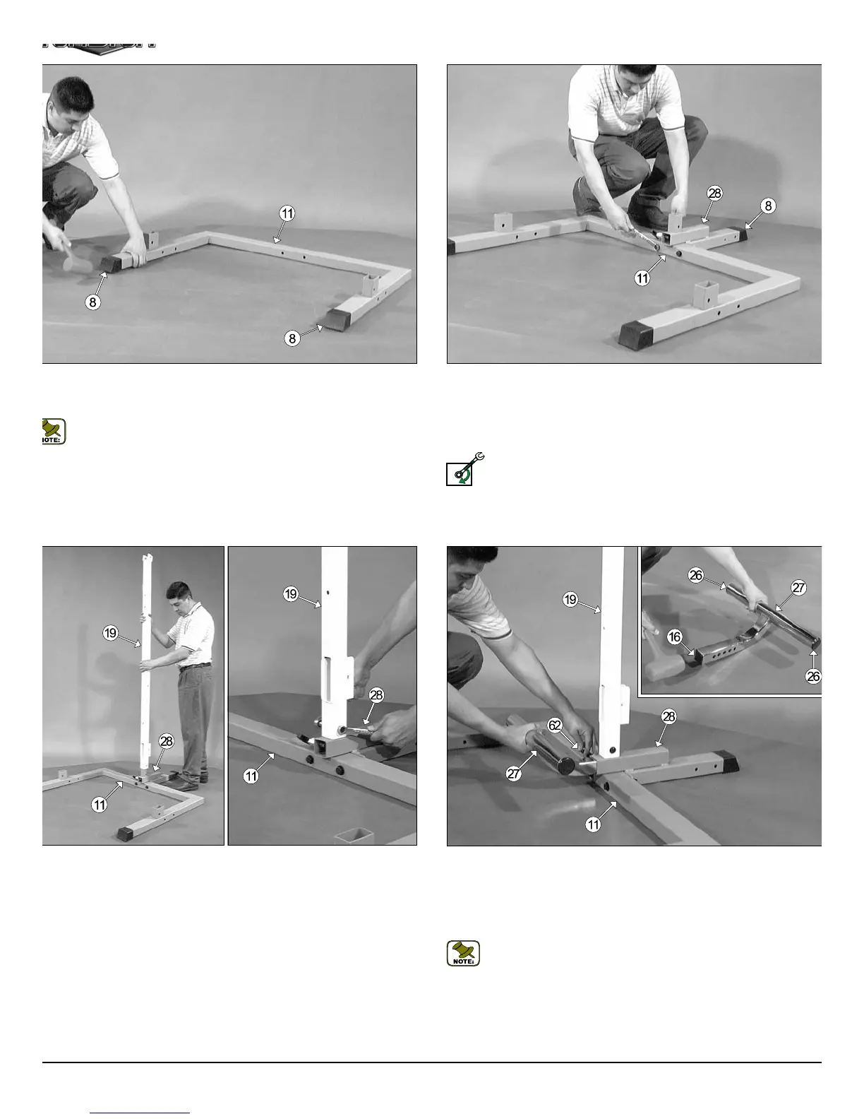
Fig. 2 Locate the Bottom Assembly Holder (#28) and, using a rubb
mallet insert one Plastic End Cap w/Groove 2 x 3 (#8) onto the tube-en
Next, attach the Bottom Assembly Holder (#28) to the Base Frame (#11
in the position as shown above, and secure it into place using two Hex He
Cap Screws 1/2-13 X 4 1/4 (#12), four Flat Washers SAE 1/2” (#10), an
two Nylon Insert Lock Nuts 1/2-13 (#9).
Loosely Fasten: Do not completely fasten this hardware assemb
at this time, as it will be completely fastened later in the assemb
process.
g. 1 On a flat surface, lay the Base Frame (#11) down and, using a
bber mallet, insert two Plastic End Caps w/Groove 2 x 3 (#8) onto the
be-ends.
Note: When positioning the Base Frame (#11) consider the com-
plete area surface of the TDH-345WS. Use the overhead view on the
cover page for designing your layout before assembling.
g. 3 Insert the Center Upright (#19) onto the receptacle located on
e Bottom Assembly Holder (#28), in the position as shown above, and
cure into place using one Hex Head Cap Screw 3/8-16 X 2 1/2 (#29), two
at Washers SAE 3/8” (#45), and one Nylon Insert Jam Lock Nut 3/8-16
46).
Fig. 4 Locate the Adjustable Foot Support (#27) and, using a rubb
mallet, insert two Plastic Insert Caps 2” Rd. (#26), and one Plastic Inse
Cap 1 3/4 “ Sq. (#16) into the tube-ends, as shown above.
Insert the Adjustable Foot Support (#27), with the selector holes facing t
Push Pull Pin 1/2” (#62), into the receptacle of the Bottom Assemb
Holder (#28).
Note: Be sure to pull the Push Pull Pin 1/2” (#62) as you perform th
assembly.
LOOSELY FASTEN
3
TDH 345 Half Cage Ensembl