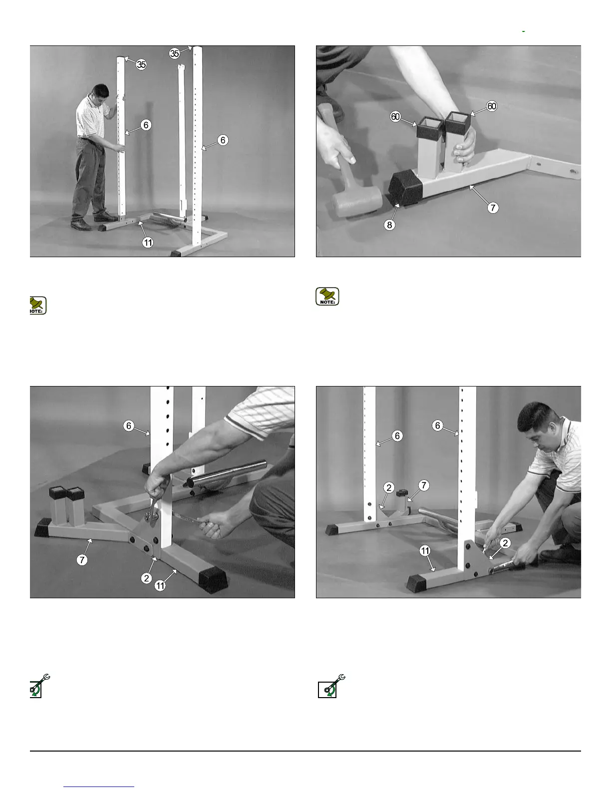
g. 5 Insert the two Selectorized Uprights (#6) onto the receptacles
cated on the Base Frame (#11), in the position as shown above with the
le pattern facing away from the unit.
Note: The two Plastic Insert Caps 2 X 3 (#35) located on top of the
Selectorized Uprights (#6) have been assembled by the factory.
Fig. 6 Using a rubber mallet, insert one Plastic End Cap w/Groove 2 X
(#8) onto the tube-end of the Accessory Rack (#7).
Note: The two Plastic Tube Guides 2” Sq. (#60) located on the A
cessory Rack (#7) have been assembled by the factory.
g. 7 Attach the Accessory Rack (#7) and a Triangular Corner Plate
2) to the Base Frame (#11), in the position as shown above, using two
ex Head Cap Screws 1/2-13 X 4 1/2 (#14), four Flat Washers SAE
2” (#10), and two Nylon Insert Lock Nuts 1/2-13 (#9). Next, affix the Trian-
lar Corner Plate (#2) to the Selectorized Upright (#6) using two Hex
ead Cap Screws 1/2-13 X 3 (#13), four Flat Washers SAE 1/2” (#10), and
o Nylon Insert Lock Nuts 1/2-13 (#9).
Loosely Fasten: Do not completely fasten this hardware assembly
at this time, as it will be completely fastened later in the assembly
process.
Fig. 8 Attach a Triangular Corner Plate (#2) to the Selectorized U
right (#6), in the position as shown above, using two Hex Head Cap Scre
1/2-13 X 3 (#13), four Flat Washers SAE 1/2” (#10), and two Nylon Inse
Lock Nuts 1/2-13 (#9). Next, affix the Triangular Corner Plate (#2) to t
Base Frame (#11), using two Hex Head Cap Screws 1/2-13 X 4 1/4 (#12
four Flat Washers SAE 1/2” (#10), and two Nylon Insert Lock Nuts 1/2-1
(#9).
Loosely Fasten: Do not completely fasten this hardware assemb
at this time, as it will be completely fastened later in the assemb
process.
ELY FASTEN
LOOSELY FASTEN
TDH 345 Half Cage Ensemble
4