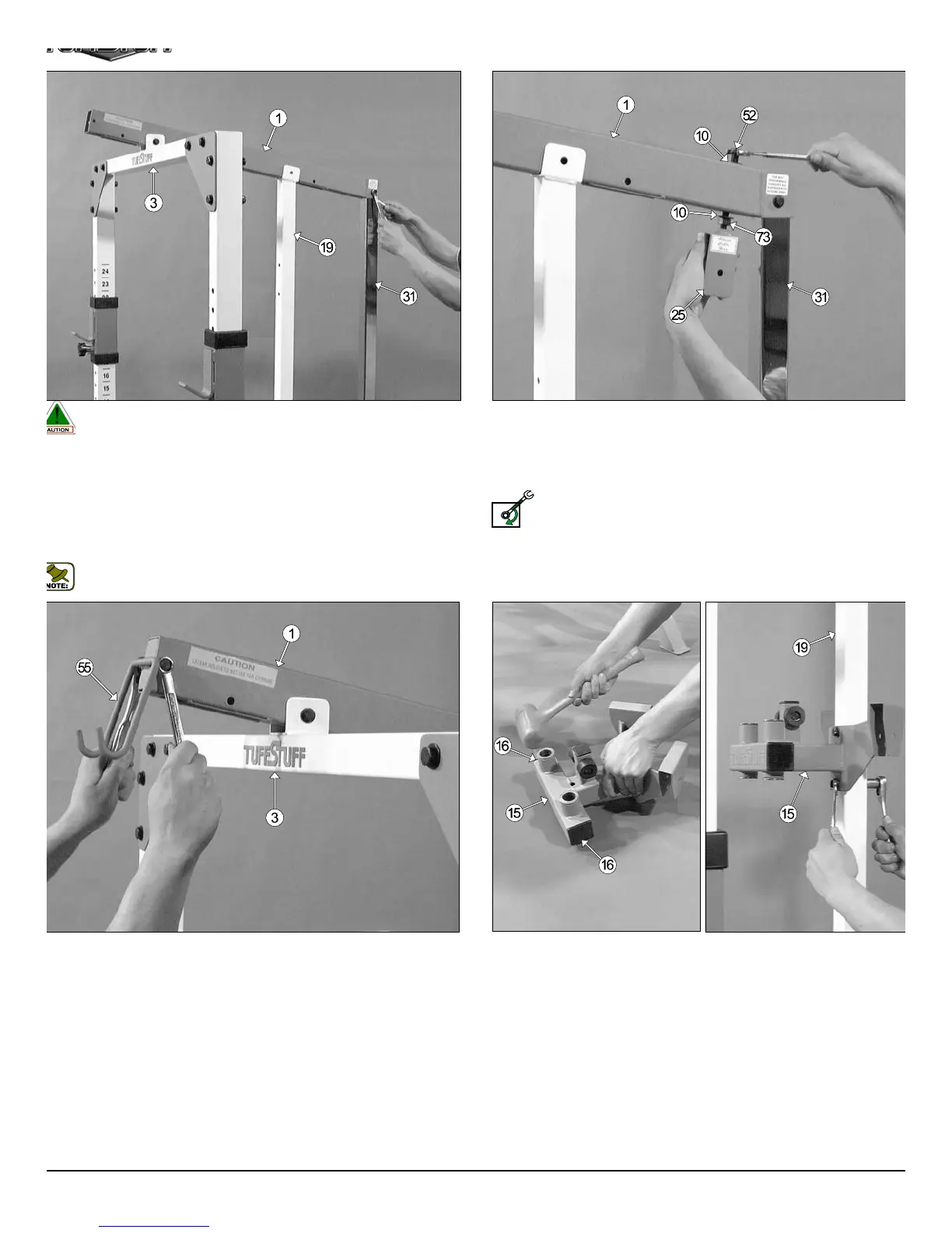
Fig. 18 Locate the Upper Swivel Bracket (#25) and thread a Regul
Hex Nut 1/2-13 (#73) and insert one Flat Washer SAE 1/2” (#10). Ne
insert the Upper Swivel Bracket (#25) into the Top Pulley Housing (#
receptacle and secure it into place using one Flat Washer SAE 1/2” (#10
and one Nylon Insert Jam Lock Nut 1/2-13 (#52).
Loosely Fasten: Do not completely fasten this hardware assemb
at this time to allow cable adjustment once the cable routing h
been completed.
LOOSELY FASTEN
Caution: It is recommended to use another person in assisting with
this assembly.
ig. 17 Insert the receptacle of the Top Pulley Housing (#1) onto the
hrome Post (#31), then mount the Top Pulley Housing (#1) into the
rackets of the Center Upright (#19), and the Top Stabilizer (#3).
ext, secure the Top Pulley Housing (#1) to the Top Stabilizer (#3), and
e Chrome Post (#31) using two Hex Head Cap Screws 3/8-16 X 2 3/4
33), four Flat Washers SAE 3/8” (#45), and two Nylon Insert Jam Lock
uts 3/8-16 (#46).
Note: Do not secure the Top Pulley Housing (#1) to the Center Up-
right (#19) at this time.
g. 19 Attach the Lat Bar Holder (#55) to the Top Pulley Housing (#1)
d secure it into place using one Hex Head Cap Screw 3/8-16 X 2 1/2
29), two Flat Washers SAE 3/8” (#45), and one Nylon Insert Jam Lock Nut
8-16 (#46).
Fig. 20 Locate the Pec Dec Housing (#15) and, using a rubber malle
insert two Plastic Insert Caps 2” SQ. (#16) into each of the tube-ends of t
Pec Dec Housing (#15).
Next, affix the Pec Dec Housing (#15) to the Center Upright (#19) a
secure it into place using two Hex Head Cap Screws 3/8-16 X 3 (#67), fo
Flat Washers SAE 3/8” (#45), and two Nylon Insert Lock Nuts 3/8-16 (#48
Refer to the Exploded View Diagram on page 18 for further illustration of th
assembly.
7
TDH 345 Half Cage Ensembl